Friday, 9 April 2010

Recently discovered issues with the IPE160 beam and alternative solutions

For the given types of load exerted on the standard IPE160 beam the deflection, BMmax and SFmax were obtained to indicate worst case conditions that the given material (steel grade) would need to withstand:


The next stage was to calculate the maxBM and maxSF for the given structural steel. If these values are found to be higher than the calculated maxBM and maxSF under load then the beam will not fail. The following formulas were used:

M = Z *("fy") where Z = I/y (for the moment)
Where “fy” = steel grade

V= "dw"*"tw"*("fy"/(3)^(1/2)) (for the shear force)

Formulas and following information courtesy of:
The Corus interactive “blue book” to BS 5950-1
BS 4: part1:1993
BS 5950-12000 part 1
Elements of Strength of Materials, International Student Edition, by S Timoshenko

To calculate the maxBM:

M = Z ("fy")
Note:
Z = I/y and y= D/2

“fy”= common steel grade S250= 250 N/mm^2
( i.e for the given 5mm thickness the required design strength is 250N/mm^2)


I=8.34E-06 m^4 or 8.34E+06 mm^4

D/2 =160mm/2= 80mm

Therefore Z =I/y = (8.34E+06 mm^4/80mm)
Z =104250mm^3

M=Z* “fy”

M=104250mm^3 * 250 N/mm^2
M=26.06E+06 Nmm
M=26.06 kNm

In order to obtain the maxBM a factor of safety rm=1.05 and rf=1.1 provided in the Corus interactive “blue book” to BS 5950-1 need to be included:

Md =M/rm*rf
Md =26.06/1.05*1.1
Md =22.5 kNm

This is the maxBM that this steel grade could withstand.

For max shear force that the beam would need to withstand:
V ="dw"*"tw"*("fy"/(3)^(1/2))
V= 5* 145.2*(250/(3)^(1/2))
V=104789N or 104.789kN

However another factor mentioned in the Corus interactive ” blue book” is to have a safety capacity related to Buckling (some tables are given ):
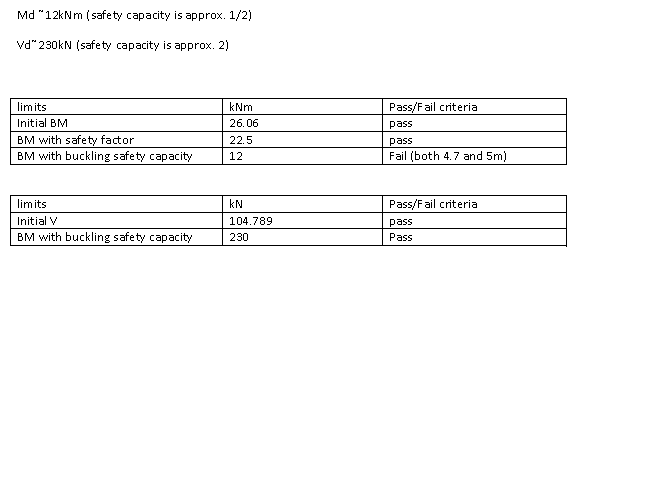


Therefore a major issue with this beam is the maxBM allowable due to consideration of safety factors and buckling.
Further research also found IPE160 to be a castellated beam type which further impacts on strength but also increases the general cost of the material.

To obtain a more suitable beam a different standard will be used and a steel grade S355:


The next stage was to calculate the maxBM and maxSF for the given structural steel. If these values are found to be higher than the calculated maxBM and maxSF under load then the beam will not fail.

I=1.356E-05 m^4 or 1.356E+07 mm^4

D/2 =177.8mm/2= 88.9mm
Therefore Z =I/y = (1.356E+07 mm^4/88.9mm)
Z=152530.9336mm^3

M=Z* “fy”

M=152530.9336mm^3 * 355 N/mm^2
M=54.148E+06 Nmm
M=54.148 kNm

In order to obtain the maxBM a factor of safety rm=1.05 and rf=1.1 provided in the “blue book” to BS 5950-1 need to be included:

Md =M/rm*rf
Md =54.148/1.05*1.1
Md =46.881 kNm

This is the maxBM that this steel grade could withstand.

For max shear force that the beam would need to withstand:
V ="dw"*"tw"*("fy"/(3)^(1/2))
V= 4.8* 146.8*(355/(3)^(1/2))
V=144422.553N or 144.423kN

However another factor mentioned in the Corus interactive "blue book” is to have a safety capacity related to Buckling (the following value is from table “4.1.3. bending. Advance UKB. Moment capacity and buckling resistance moment for Advance 355”):

Md =17kNm


This beam clearly passes the basic required criteria and so long as these loading conditions are maintained it should not fail for the duration of the service for the disaster relief (if a 4.7m beam were to be used the buckling resistance moment would be higher than 17kNm).

The following are the lists of tables used from the BS standards :


Wednesday, 7 April 2010

Abdi Elmi - IPE160

From calculations we’ve done we found that the most suitable beam is the IPE160. Using its properties the IPE160 is ideal with the beam length to be 4.7m. Researching the web, the cost for this type of beam is very vague due to the fact that you have to contact the suppliers (mostly living in east-Asia) for a ‘negotiable’ price. One example of these sorts of websites is: ecplaza.net/tradeleads/seller/6010942/ipe140ipe160_ipe180_ipe200.html. This is a problem that we need to discuss in our next meeting.

There are three structural steel types that I’ve been researching on the net. The steel grade S274, S355 and S460. Almost all UK structural steels are the S275 and the S355. The letters and numbers are:


(S) Structural and (three digit numbers)Yield Strength (Newton/mm squared)

Here’s a table I’ve constructed of each steel grade’s properties:

Steel grade

Yield-min (MPa)

Tensile-max (MPa)

S275

275

580

S355

355

680

S460

460

670

One task that i'll have to do is find the prices for these steel grades and see which one is most suitable for our particular crane.

Saturday, 3 April 2010

references for calculations

The following scanned images are from 2 selected books which have been used to obtain the equations used to calculate the stresses and deflections for the boom.

Courtesy of:
Mechanics of engineering materials, second edition, by PP Benham, RJ Crawford & CG Armstrong;
Elements of Strength of Materials, International Student Edition, by S Timoshenko;

In order to obtain the following equations in the calculations:


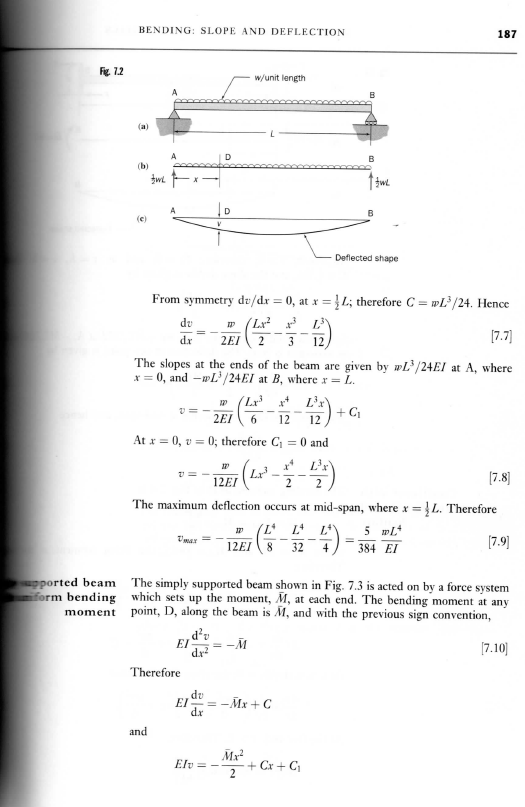
A formula sheet from "Elements of Strength of Materials, International Student Edition, by S Timoshenko" where by the principle of superposition two factors (deflection due to a uniformly distributed load and deflection due to a point load) were combined providing the final deflection value.


The theory of superposition is explained in the following paragraphs along with the diagrams provide a visual image of how the beam will behave when subjected to varying loads (this is an important situation as it's behaviours in the following example are very similar to the behaviours we could expect our crane to experience):


The following scans are proofs of the formula obtained for the varying deflection loads and can be used as a template for our mathematical equations (for double checking values or if an error was made in the final value where could it have occurred by following the template).

For a point load our calculations would need to follow the following format:


For a uniformly distributed load the calculations would need to follow the following format:


For the particular type of I beam our crane will be using, due to the shape we have selected, it was required to use the following formula for is second moment of area.


However in order to find the maximum bending moment and the maximum shear force the following diagrams were used along with the knowledge that maximum bending moment will occur when the 1000kg load is placed in the middle of the beam and that the max shear force when the load is placed at its ends:


the diagrams and calculations allowed through the theory of superposition to combine:
for max shear:
Pa/l (for point load where a=l)+ wl/2 (uniform load)
therefore obtaining the equation: wl/2 + P

for max BM:
(Pab)/l (for point load where a=l/2 and b=l/2) + (wl^2)/8
Therefore obtaining the equation: (wl^2)/8 +Pl/4


The final thing which would need to be calculated is the max BM and SF that the particular beam we have selected can handle due to its dimensions and type of structural steel component. ( if these values are higher than the ones obtained for the calculations that our beam will create with its load, it will mean the beam is safe to use under these conditions as it will not fail under them):


the following equations will be used:
M = Z ("fy") where Z = I/y (for the moment)
V= "dw""tw"("fy"/(3)^(1/2))

"fy"= specific design strength of the steel selected from a list of steel grades (e.g. are given on previous blogs)

Another factor that could be calculated in its stead includes the working stress at a distance point y. It would need to be found using the yield point or ultimate tensile stress for that particular grade of steel and divide it by a safety factor e.g. 2 (as given in the example). This will ensure that the steel will remain in the safe elastic region and avoid becoming permanently deformed.

Friday, 2 April 2010

calculations for IPE 160 beam and legs

To find the stresses on each leg, I had to go over the calculations for the IPE160 beam using the dimensions sandy published. This also gave me a chance to check sandy's answers (they are all correct). The calculations show that the maximum amount of stress experienced by any part of the legs is 4.818mpa. The lowest compressive yield strength for an aluminium alloy that I have come across is 105mpa, therefore this comfirms that the vast majority aluminium alloys would be able to be used on the legs.Now its just a question of finding the most cost effective one.


Minutes of meeting (02/04/2010)

Members attended to discuss the current situation with selecting appropriate beams for the glide rail and will be posting up research for the selected beam, including costing and material.

The legs will have further refined calculations which will be posted at a later date and allow final costing calculations to be made.

The following members attended, those not present had given reasons for not being able to attend at an earlier date and will be informed of any required work:
Sandra Donohoe - Project Manager
Jarrett Doherty - Materials Specialist
Abdi Elmi - Finance Officer

Calculations for the glide rail

The following are the formulas used in the calculations for the designed boom of the crane:


Equations courtesy of:

http://www.efunda.com/math/areas/SquareIBeam.cfm

Mechanics of engineering materials, second edition, by PP Benham, RJ Crawford & CG Armstrong

Elements of Strength of Materials, International Student Edition, by S Timoshenko

Legend
E – Young’s modulus of the material (Pa)
I – second moment of area (m^4)
w – Uniformly distributed load (N/m)
P –point load (N)
L –total length of glide rail (m)

Using the properties of superposition it is possible to obtain the combined loading effect on a structure by adding the individual effects caused by the different loading conditions.


Courtesy of:
Mechanics of engineering materials, second edition, by PP Benham, RJ Crawford & CG Armstrong

Elements of Strength of Materials, International Student Edition, by S Timoshenko

The ORIGINAL I BEAM possesses the following values:


This particular glide rail beam possesses several disadvantages, particularly the total mass. This would make it difficult to be carried by 4 people over 100m of rough ground. The deflection however complies with the BS 5950-12000 part 1:


The maximum deflection for the given length would be 5.1m/180=0.02833m.

Several improvements would need to be carried out on the beam particularly choosing a beam with a low manufacturing cost. Currently choosing this type of beam would have large cost implications due to its custom made quality.

Alternative options were therefore researched (courtesy of http://www.structural-drafting-net-expert.com/steel-selections-IPE.html):


Using the values of the original I beam structure as a template three standards were chosen IPE140, IPE120 and IPE160.
These were also selected as the beam width fell within an acceptable range 50-220mm to be able to use the selected travel trolleys for the hoists.

The following results were obtained:


From these calculations it can be deduced that not only has an effect been created on the mass but also on the deflection value, falling within the acceptable range.

According to the standard, the new max deflection value= 4.7m/180=0.02611.

The length was selected due to the dimensions of the loads that will be dealt with.

It is likely that beam IPE140 will not be used in the final design as the deflection is too close to the upper range of the specified BS 5950-12000 part 1 standard.


As we can see the mass has decreased to a weight which could be carried by 2 people however the I beam dimensions caused the deflection to be greater than the accepted standard for structural steel. Therefore beam IPE120 will not be used in the final design.


It is clear from these results and from the δmax equation that the higher the second moment of area the lower the deflection but the greater the area and the overal mass of the beam, an appropriate balace always needs to be found.

Hoist types and costs

Research was carried out into the type of winch or hoists that would be used and the possibility of using a travel trolley.

The following manual hoists were initially researched and the following information obtained from the site (http://www.hoistsdirect.com/):


The following information was obtained for powered hoists from (http://www.hoistsdirect.com/):


As these prices are far too expensive for the type of budget in question as well as having too high a mass to be used for this type of project, it was considered to buy the trolley component and winch/hoist components as separate items (http://www.keyonline.co.uk):

The following link (http://www.keyonline.co.uk/manual_c_Main006004001.html) lists some of the possible manual hoist options.

Further details are found in their catalogue page (http://static.manutangroup.com/KEY/en_GB/PDF/281.pdf)

The most popular including:


An alternative including the use of electronic winches, from catalogue (http://static.manutangroup.com/KEY/en_GB/PDF/285.pdf):


The electric winch would prove advantageous as it would lift a load more rapidly than a manual hoist. However it is far more costly and may be unnecessary for the situation at hand as it would be acceptable for the manual hoist to lift the item several cm from the ground, enough not to be blocked by anything in its path but low enough for safety reasons of the workers.

Out of the two manual hoists the best suited would be the Manual Hoist. The reasons are purely safety and convenience, as the Ratchet Lever Hoist would require more effort from the workers and closer contact to the load increasing safety risks while the manual hoist can be operated at a greater distance:

http://www.e-rackonline.com/product_images/1210.jpg

The next thing which would need to be considered is the trolley system which would allow the hoist to “hook” onto (http://static.manutangroup.com/KEY/en_GB/PDF/280.pdf):


Respectively each has their own advantages and disadvantages, which would need to be individually considered.

The masses of the combined system are lowered in the following manner:
manual hoist (11.7 kg) + push travel trolleys (9-16kg) =total mass range (20.7-27.7 kg)
manual hoist (11.7 kg) + geared travel trolleys (11.2-18kg) =total mass range (22.9-29.7 kg)

The Geared travel trolley is more expensive but provides more control when moving the load. The push travel trolley would need more support however it costs less and the following design could be looked into in order to avoid certain problems:


The beam width section is also important to consider as it will influence the type of I beam that can be used. The beam width most applicable would need to be in the range 50-220mm to be able to use these trolleys.