The style chosen was a gantry crane; with a lightweight, easily assembled, and easily repaired frame. The design minimises the number of small components whilst maintaining fitness to purpose. The overall design of this crane is described in fig 1.
FIG 1: Exploded Crane Design
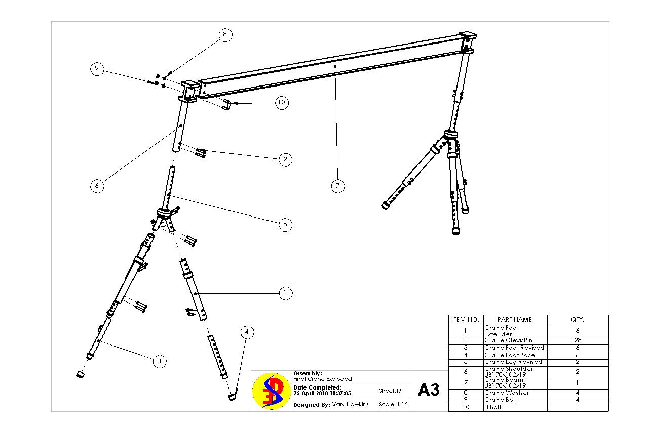
The individual components are described in detail below. All components will be painted with an epoxy mastic primer for protection from scratching and erosion.
The first component is the foot extender depicted in fig 2. This component connects the foot to the leg, and acts essentially as a spacer. This component is made from 7050 Aluminium with the dimensions and tolerances shown.
FIG 2: Crane Foot Extender (six in pack)

Component two is a standard dimension clevis pin. The stresses on this pin are low and so the most economically viable standard metal clevis pin at the time off manufacture will be provided. The pin must be M20 with a length no less than 80mm. There are twenty eight of these in the pack.
Component 3, depicted in fig 3, is the revised foot. This component connects the foot extender to the foot base, and has a series of holes drilled up its shaft. This allow the height of this section of the leg to be easily adjusted to fit the terrain by slotting the clevis pins through the foot extender and then through different sets of adjacent holes on this foot piece. This component is also made from 7050 Aluminium with the dimensions and tolerances shown.
FIG 3: Crane Foot (six in pack)

The next component is the crane foot base, depicted in fig 4. This is a rubber stopper with a textured finish fitted on the end of the crane foot, which creates friction with the ground to ensure good surface contact. This component comes in several forms, as required by the client, however fig 4 depicts its standard orientation.
FIG 4: Crane Foot Base (six in pack)

Component five is the revised crane leg, shown in fig 5. The base of this component attaches the the crane foot extender, and the top has a series of holes drilled up its shaft. This allow the height of this section of the leg to be easily adjusted to meet the needs of the assembly team by slotting the clevis pins through the shoulder first, then through different sets of adjacent holes on this leg. This component is also made from 7050 Aluminium with the dimensions and tolerances shown.
FIG 5: Crane Leg (two in pack)

The sixth component is the crane shoulder designed to fit the UB 178x102x19 standard beam, depicted fig 6. The base of this component was designed to attach to the leg via clevis pins, and the head was designed to act as a built in wall for the beam to attach via a U bolt. The head design may be simplified upon clients request to minimise manufacturing cost, though the current orientation is the strongest option. This component is made from 7050 Aluminium with the dimensions and tolerances shown.
FIG 6: Crane Shoulder (two in pack)

The beam component, depicted fig seven, was designed to match the British standard UB 178x102x19 I beam. The standardisation of this component will lower the pack cost, and increase the clients ability to replace the beam should it be damaged or lost. This component is made from Steel with the dimensions and tolerances shown.
FIG 7: Crane Beam UB 178x102x19 (one in pack)

The final three components are the washers, nuts, and U bolts for the beam respectively. These are standard metal M20 components which, as with the clevis pins, will be sourced from the most economically viable source at the time off manufacture. There are two of each of these in the pack.
Fig 8 depicts a unpainted image of the crane in a disaster zone situation.
FIG 8: Crane in the Field

The hoist and travel trolley will be supplied if requested, though as these are standard size components to fit the UB178x102x19 beam they may be sourced independently if the client wishes. Self-sourcing will reduce the cost of purchase accordingly.