Showing posts with label Design Process. Show all posts
Showing posts with label Design Process. Show all posts
Thursday, 29 April 2010
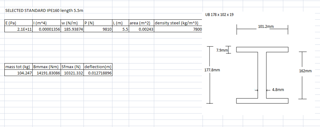
Final dimension sizes for I beam
The following table lists the final dimansions, mass, deflection, Maximum Shear force and Bending moment that the beam used for the crane would have (within BS 5950-1 limits)


Exploded crane animation
This is the animation describing the assembly of the crane.
The colour scheme is arbitrary in this video, designed to allow the viewer to differentiate easily between components.
Saturday, 24 April 2010
Formal Engineering Drawings Templates
The follow image is the engineering drawing template for the crane components. The company logo is yet to be inserted, but all other elements are as they will be in the formal proposal.
 The next image is of the engineering drawing template for the crane assemblies, one will be standard and the other one will be exploded.
 This drawing template also requires the company logo, though is also otherwise as the final assembly drawings will be presented.
The blue text represents links to the part designs, which will be automatically replaced with the appropriate information.
The next image is of the engineering drawing template for the crane assemblies, one will be standard and the other one will be exploded.This drawing template also requires the company logo, though is also otherwise as the final assembly drawings will be presented.The blue text represents links to the part designs, which will be automatically replaced with the appropriate information.
Sunday, 18 April 2010
Sectioned Beams
According to BS 5950-12000 part 1 it is also possible to carry out the following design in order to split the beam into several sections:

This would create several issues including stress concentrations and movement hindrance of trolley, as there is only a small clearance available between the trolley and the beam in order to allow successful and controlled movement.


This would create several issues including stress concentrations and movement hindrance of trolley, as there is only a small clearance available between the trolley and the beam in order to allow successful and controlled movement.

Saturday, 17 April 2010
Load dimensions
To obtain an approximate maximum length for the glide beam the 4m travelling distance needs to be taken account of along with any other clearances for load and shoulder joints total approx 290mm.

For the worst case scenarios of loading conditions, the two most probable loads (rubble) include reinforced concrete and steel I beams.
Using the BS 5950 standards, [Limit State Design of Reinforced Concrete By B. C. Punmia, Arun Kumar Jain, Arun Kr. Jain, Ashok Kr. Jain] to find common dimension sized beams e.g.

Approximate steel: concrete ratio would need to be estimated to calculate volumes, and the missing Z dimension. Based on several different pre-stressed processes, wire dimensions...
Processes from [Limit State Design of Reinforced Concrete By B. C. Punmia, Arun Kumar Jain, Arun Kr. Jain, Ashok Kr. Jain]:


Approximate dimensions sizes were hence obtained:

The final ‘z’ dimension would need to be calculated. The following parameters are taken into account:

Calculations of dimensions to give a load of approximately 1 tonne:
Steel
5% of the cross sectional area =0.0045m^2
Assume Z=4m to obtain volume for the following equation:
Mass = Volume * Density
Mass= (0.0045*4)m^3*(7800) kg/m^3
Mass=140.4kg
Concrete
95% of the cross sectional area=0.0855m^2
Assume Z=4m to obtain volume for the following equation:
Mass = Volume * Density
Mass= (0.0855m *4)m^3*(2400) kg/m^3
Mass=820.8kg
Total mass = 140.4kg + 820.8kg= 961.2kg
In order to obtain the desired mass approximately a 4% increase in length would be required, hence obtaining:
Steel
5% of the cross sectional area =0.0045m^2
Assume Z=4.16m to obtain volume for the following equation:
Mass = Volume * Density
Mass= (0.0045*4.16)m^3*(7800) kg/m^3
Mass=146.016kg
Concrete
95% of the cross sectional area=0.0855m^2
Assume Z=4.16m to obtain volume for the following equation:
Mass = Volume * Density
Mass= (0.0855m *4.16)m^3*(2400) kg/m^3
Mass=853.632kg
Total mass = 146.016kg + 853.632kg = 999.648kg
Hence the length Z required of the load that would need to be lifted is approx 4.16m.
Another possibility is to find several shorter sections and hoist them together or one wider section with the following dimensions:

Z would be approximately 2m.
Steel I beams
The following data was obtained from http://www.engineeringtoolbox.com/british-universal-steel-columns-beams-d_1316.html:

A standard I beam was selected for the worst scenario load that could be found and require lifting (this particular beam was selected as it poses the greatest load risk as it could potentially surpass the 1 tonne requirement)
Calculate Z length
1000kg/238.1 kg/m = 4.19m (length that would need to be found to pose issues to the crane)
From these calculations a total clearance of approximately 300 -400mm may be required to be able to lift most available loads safely from a to b.
It will be assumed that these loads will be lifted from their midsection (centre of gravity) to maintain safety.

Another issue which would need to be addressed is the following:


For the worst case scenarios of loading conditions, the two most probable loads (rubble) include reinforced concrete and steel I beams.
Using the BS 5950 standards, [Limit State Design of Reinforced Concrete By B. C. Punmia, Arun Kumar Jain, Arun Kr. Jain, Ashok Kr. Jain] to find common dimension sized beams e.g.

Approximate steel: concrete ratio would need to be estimated to calculate volumes, and the missing Z dimension. Based on several different pre-stressed processes, wire dimensions...
Processes from [Limit State Design of Reinforced Concrete By B. C. Punmia, Arun Kumar Jain, Arun Kr. Jain, Ashok Kr. Jain]:


Approximate dimensions sizes were hence obtained:
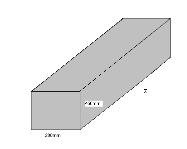
The final ‘z’ dimension would need to be calculated. The following parameters are taken into account:

Calculations of dimensions to give a load of approximately 1 tonne:
Steel
5% of the cross sectional area =0.0045m^2
Assume Z=4m to obtain volume for the following equation:
Mass = Volume * Density
Mass= (0.0045*4)m^3*(7800) kg/m^3
Mass=140.4kg
Concrete
95% of the cross sectional area=0.0855m^2
Assume Z=4m to obtain volume for the following equation:
Mass = Volume * Density
Mass= (0.0855m *4)m^3*(2400) kg/m^3
Mass=820.8kg
Total mass = 140.4kg + 820.8kg= 961.2kg
In order to obtain the desired mass approximately a 4% increase in length would be required, hence obtaining:
Steel
5% of the cross sectional area =0.0045m^2
Assume Z=4.16m to obtain volume for the following equation:
Mass = Volume * Density
Mass= (0.0045*4.16)m^3*(7800) kg/m^3
Mass=146.016kg
Concrete
95% of the cross sectional area=0.0855m^2
Assume Z=4.16m to obtain volume for the following equation:
Mass = Volume * Density
Mass= (0.0855m *4.16)m^3*(2400) kg/m^3
Mass=853.632kg
Total mass = 146.016kg + 853.632kg = 999.648kg
Hence the length Z required of the load that would need to be lifted is approx 4.16m.
Another possibility is to find several shorter sections and hoist them together or one wider section with the following dimensions:

Z would be approximately 2m.
Steel I beams
The following data was obtained from http://www.engineeringtoolbox.com/british-universal-steel-columns-beams-d_1316.html:

A standard I beam was selected for the worst scenario load that could be found and require lifting (this particular beam was selected as it poses the greatest load risk as it could potentially surpass the 1 tonne requirement)
Calculate Z length
1000kg/238.1 kg/m = 4.19m (length that would need to be found to pose issues to the crane)
From these calculations a total clearance of approximately 300 -400mm may be required to be able to lift most available loads safely from a to b.
It will be assumed that these loads will be lifted from their midsection (centre of gravity) to maintain safety.

Another issue which would need to be addressed is the following:

Exploded Third Crane Design
The image below shows the exploded view of the third and final crane design. This image also contains a list of components and their quantities.

Tuesday, 13 April 2010
Crane Foot Base Options
The following image is a rendered picture of four potential crane foot base options.

These foot bases will be analysed from left to right:
- The first is the original foot base, as described by the previous CAD drawings. This foot base is quite basic and versatile, though since it will be supporting the crane foot on an angle it may be prone to slippage in wet conditions.
- The second is a revised foot base. This foot base has been slanted to the angle of the crane foot. The bottom has also been altered to have a series of groves, increasing the friction of the foot base with the ground. This design would greatly improve the stability of the crane, though would require a small flat surface to rest upon. It would also require orientating to the angle of the crane foot.
- The third design is a modified version of the previous design with all the same benefits over the original design. However this design has a reduced surface area of contact, thus the area beneath the foot base need not be as flat. This however may slightly reduce the stability of the crane, and this type also requires orientating.
- The final design is a spike design. This would be particularly useful in soft ground to help anchor the crane, however it would be useless on a solid surface such as concrete or tarmac.
In conclusion, I believe that since these foot bases have been designed to be removable, multiple types should be provided in the pack to suit different situations. I will take this matter up with the rest of the team in the next group meeting.
These foot bases will be analysed from left to right:
- The first is the original foot base, as described by the previous CAD drawings. This foot base is quite basic and versatile, though since it will be supporting the crane foot on an angle it may be prone to slippage in wet conditions.
- The second is a revised foot base. This foot base has been slanted to the angle of the crane foot. The bottom has also been altered to have a series of groves, increasing the friction of the foot base with the ground. This design would greatly improve the stability of the crane, though would require a small flat surface to rest upon. It would also require orientating to the angle of the crane foot.
- The third design is a modified version of the previous design with all the same benefits over the original design. However this design has a reduced surface area of contact, thus the area beneath the foot base need not be as flat. This however may slightly reduce the stability of the crane, and this type also requires orientating.
- The final design is a spike design. This would be particularly useful in soft ground to help anchor the crane, however it would be useless on a solid surface such as concrete or tarmac.
In conclusion, I believe that since these foot bases have been designed to be removable, multiple types should be provided in the pack to suit different situations. I will take this matter up with the rest of the team in the next group meeting.
Monday, 12 April 2010
Painting Safety Note
It is worth noting that since the legs are made from aluminium, it is necessary to adopt caution when choosing a primer paint. The following formula describes the oxidation of aluminium:
Fe2O3 + 2Al → 2Fe + Al2O3 + heat
When ignited, this reaction of aluminium and iron oxide produces liquid iron which can melt though almost anything. The military would call such a mixture thermite, and it would be used in incendiary devices.
This reaction would occur if the crane legs were painted with an iron oxide based primer paint such as Red Oxide. This particular type of paint is a common primer when painting metals, however it would be highly inappropriate to paint aluminium with it in a disaster zone where there would like be many large and uncontrolled fires.
The type of primer more suited to this environment would be an Epoxy Mastic metal primer or similar.
Fe2O3 + 2Al → 2Fe + Al2O3 + heat
When ignited, this reaction of aluminium and iron oxide produces liquid iron which can melt though almost anything. The military would call such a mixture thermite, and it would be used in incendiary devices.
This reaction would occur if the crane legs were painted with an iron oxide based primer paint such as Red Oxide. This particular type of paint is a common primer when painting metals, however it would be highly inappropriate to paint aluminium with it in a disaster zone where there would like be many large and uncontrolled fires.
The type of primer more suited to this environment would be an Epoxy Mastic metal primer or similar.
Potential Changes to Third Shoulder Design
The following image describes three possibilities for the third crane shoulder.

They are as follows:
-The one on the left is the design described in detail in my previous post
-The middle one is the same as the first, only with the top removed. This would reduce manufacturing cost and weight, though as the anchoring system of the shoulder to the beam is now essientially an open system, this woyuld significantly decrease the strength.
-The one on the right is a box design, essentially the same as the first design except in one solid block. This would increase the stability of the anchoring of the beam into the shoulder, though at the same time would significantly increase the cost of manufacture and the weight of the leg as a whole.
In conclusion I believe the original design is the most suitable, though in order to be certain this requires farther stress analysis to find the best design.

They are as follows:
-The one on the left is the design described in detail in my previous post
-The middle one is the same as the first, only with the top removed. This would reduce manufacturing cost and weight, though as the anchoring system of the shoulder to the beam is now essientially an open system, this woyuld significantly decrease the strength.
-The one on the right is a box design, essentially the same as the first design except in one solid block. This would increase the stability of the anchoring of the beam into the shoulder, though at the same time would significantly increase the cost of manufacture and the weight of the leg as a whole.
In conclusion I believe the original design is the most suitable, though in order to be certain this requires farther stress analysis to find the best design.
Sunday, 11 April 2010
Third Crane Shoulder Design
This is the third design for the crane shoulder. The dimensions have been altered to fit the UB178x102x19 beam. The dimensions of the holes for the pins are currently arbitrary as I am awaiting the pin analysis, however all other elements are dimensioned correctly.


The following image is a comparison between the second (pictured to the left) and third (to the right) shoulder design.

This third design is described in more detail in the engineering drawing below.

The crane is now slightly taller than before, though with this standardised beam will have far more options concerning the choice of winch mechanism. The image below describes the assembled crane, without the beam pins.

Friday, 9 April 2010
CAD UB178x102x19 Crane Beam
These are the CAD images and drawings of the UB178x102x19 Crane Beam. Firstly we have an image of the revised crane beam (left of image) compared to the UB178x102x19 Crane Beam (right of image).

In addition, here is the engineering drawing for this standard beam. The holes for the beam pins are M20 and just over three times the distance from the end of the beam as their diameter.

The use of a standard dimensioned beam will dramatically reduce cost, compared with a custom beam, and also make it considerably easier to find a winch system to fit the beam dimensions.

In addition, here is the engineering drawing for this standard beam. The holes for the beam pins are M20 and just over three times the distance from the end of the beam as their diameter.


The use of a standard dimensioned beam will dramatically reduce cost, compared with a custom beam, and also make it considerably easier to find a winch system to fit the beam dimensions.
Beam pins
The beam pins are inefficiently designed, and will be changed on CAD shortly. They will be altered to a standard size HEX head bolt, such as one from the list show on the following link, to considerably reduce their cost in comparison to the cost of custom made pins.

http://uk.rs-online.com/web/search/searchBrowseAction.html?method=retrieveTfg&Ne=4294957938&Nr=AND%28avl%3auk%2csearchDiscon_uk%3aN%29&N=4294962569+4294955562+4294905479&Ns=stockPolicy_uk%7c1%7c%7cnew_uk%7c1&binCount=85&multiselectParam=4294962569%204294955562&selectAttribute=M20#breadCrumb
Another option for the pin design is to use a Clevis pin system

http://uk.rs-online.com/web/search/searchBrowseAction.html?method=browseSubRange&Ne=4294953839&N=4294947005&productNum=0838940
Alternatively, to reduce the number of components in the crane pack (as small parts may be lost) a U bolt system could be employed

http://uk.rs-online.com/web/search/searchBrowseAction.html?method=retrieveTfg&binCount=7&Ne=4294957561&Ntt=u+bolt&Ntk=I18NAll&Nr=AND%28avl%3auk%2csearchDiscon_uk%3aN%29&Ntx=mode%2bmatchallpartial&N=4294955388&Nty=1
The beam dimensions have once again been altered and so a revised CAD representation will also be posted here shortly, as well as any other changes to the design proposed by the stress analysis (including limits and fits which will be added as they are calculated)

http://uk.rs-online.com/web/search/searchBrowseAction.html?method=retrieveTfg&Ne=4294957938&Nr=AND%28avl%3auk%2csearchDiscon_uk%3aN%29&N=4294962569+4294955562+4294905479&Ns=stockPolicy_uk%7c1%7c%7cnew_uk%7c1&binCount=85&multiselectParam=4294962569%204294955562&selectAttribute=M20#breadCrumb
Another option for the pin design is to use a Clevis pin system

http://uk.rs-online.com/web/search/searchBrowseAction.html?method=browseSubRange&Ne=4294953839&N=4294947005&productNum=0838940
Alternatively, to reduce the number of components in the crane pack (as small parts may be lost) a U bolt system could be employed

http://uk.rs-online.com/web/search/searchBrowseAction.html?method=retrieveTfg&binCount=7&Ne=4294957561&Ntt=u+bolt&Ntk=I18NAll&Nr=AND%28avl%3auk%2csearchDiscon_uk%3aN%29&Ntx=mode%2bmatchallpartial&N=4294955388&Nty=1
The beam dimensions have once again been altered and so a revised CAD representation will also be posted here shortly, as well as any other changes to the design proposed by the stress analysis (including limits and fits which will be added as they are calculated)
Changes to design
Certain design features which need to be brought to the attention of the group, as could potentially reduce stresses on certain structures, increase stability or for safety. The following cases for consideration will be brought up in the next meeting:
The following alteration must be made:

Obtained from BS5950-12000part1
Nut and Bolt

Leg design

Hole design -choice

Matts

The following alteration must be made:

Obtained from BS5950-12000part1
Nut and Bolt

Leg design

Hole design -choice

Matts

Friday, 2 April 2010
Hoist types and costs
Research was carried out into the type of winch or hoists that would be used and the possibility of using a travel trolley.
The following manual hoists were initially researched and the following information obtained from the site (http://www.hoistsdirect.com/):

The following information was obtained for powered hoists from (http://www.hoistsdirect.com/):

As these prices are far too expensive for the type of budget in question as well as having too high a mass to be used for this type of project, it was considered to buy the trolley component and winch/hoist components as separate items (http://www.keyonline.co.uk):
The following link (http://www.keyonline.co.uk/manual_c_Main006004001.html) lists some of the possible manual hoist options.
Further details are found in their catalogue page (http://static.manutangroup.com/KEY/en_GB/PDF/281.pdf)
The most popular including:

An alternative including the use of electronic winches, from catalogue (http://static.manutangroup.com/KEY/en_GB/PDF/285.pdf):

The electric winch would prove advantageous as it would lift a load more rapidly than a manual hoist. However it is far more costly and may be unnecessary for the situation at hand as it would be acceptable for the manual hoist to lift the item several cm from the ground, enough not to be blocked by anything in its path but low enough for safety reasons of the workers.
Out of the two manual hoists the best suited would be the Manual Hoist. The reasons are purely safety and convenience, as the Ratchet Lever Hoist would require more effort from the workers and closer contact to the load increasing safety risks while the manual hoist can be operated at a greater distance:

http://www.e-rackonline.com/product_images/1210.jpg
The next thing which would need to be considered is the trolley system which would allow the hoist to “hook” onto (http://static.manutangroup.com/KEY/en_GB/PDF/280.pdf):
Respectively each has their own advantages and disadvantages, which would need to be individually considered.
The masses of the combined system are lowered in the following manner:
manual hoist (11.7 kg) + push travel trolleys (9-16kg) =total mass range (20.7-27.7 kg)
manual hoist (11.7 kg) + geared travel trolleys (11.2-18kg) =total mass range (22.9-29.7 kg)
The Geared travel trolley is more expensive but provides more control when moving the load. The push travel trolley would need more support however it costs less and the following design could be looked into in order to avoid certain problems:

The beam width section is also important to consider as it will influence the type of I beam that can be used. The beam width most applicable would need to be in the range 50-220mm to be able to use these trolleys.
The following manual hoists were initially researched and the following information obtained from the site (http://www.hoistsdirect.com/):

The following information was obtained for powered hoists from (http://www.hoistsdirect.com/):

As these prices are far too expensive for the type of budget in question as well as having too high a mass to be used for this type of project, it was considered to buy the trolley component and winch/hoist components as separate items (http://www.keyonline.co.uk):
The following link (http://www.keyonline.co.uk/manual_c_Main006004001.html) lists some of the possible manual hoist options.
Further details are found in their catalogue page (http://static.manutangroup.com/KEY/en_GB/PDF/281.pdf)
The most popular including:

An alternative including the use of electronic winches, from catalogue (http://static.manutangroup.com/KEY/en_GB/PDF/285.pdf):

The electric winch would prove advantageous as it would lift a load more rapidly than a manual hoist. However it is far more costly and may be unnecessary for the situation at hand as it would be acceptable for the manual hoist to lift the item several cm from the ground, enough not to be blocked by anything in its path but low enough for safety reasons of the workers.
Out of the two manual hoists the best suited would be the Manual Hoist. The reasons are purely safety and convenience, as the Ratchet Lever Hoist would require more effort from the workers and closer contact to the load increasing safety risks while the manual hoist can be operated at a greater distance:

http://www.e-rackonline.com/product_images/1210.jpg
The next thing which would need to be considered is the trolley system which would allow the hoist to “hook” onto (http://static.manutangroup.com/KEY/en_GB/PDF/280.pdf):
Respectively each has their own advantages and disadvantages, which would need to be individually considered.
The masses of the combined system are lowered in the following manner:
manual hoist (11.7 kg) + push travel trolleys (9-16kg) =total mass range (20.7-27.7 kg)
manual hoist (11.7 kg) + geared travel trolleys (11.2-18kg) =total mass range (22.9-29.7 kg)
The Geared travel trolley is more expensive but provides more control when moving the load. The push travel trolley would need more support however it costs less and the following design could be looked into in order to avoid certain problems:

The beam width section is also important to consider as it will influence the type of I beam that can be used. The beam width most applicable would need to be in the range 50-220mm to be able to use these trolleys.
Wednesday, 24 March 2010
Mark Hawkins - Second Design CAD Drawings
The following are the CAD drawings for the components of this second design. The first image is of this crane assembled, and the next ten are the individual components. The last sheet is an assembly sheet showing how the crane goes together.


The dimensions and angles described by these designs have been calculated by the stress analyst, though they are still awaiting materials analysis and corresponding approval from finance. Once these tasks have been completed, the materials information will be added to the drawings and any final alterations will be made.


The dimensions and angles described by these designs have been calculated by the stress analyst, though they are still awaiting materials analysis and corresponding approval from finance. Once these tasks have been completed, the materials information will be added to the drawings and any final alterations will be made.
Subscribe to:
Posts (Atom)