This module has been well informative and allowed the group to successfully design a crane to fit a given brief, in accordance to BS standards.
It was important to choose the most suitable crane design from the large variety found in the first week: gantry, jib, tower crane, bridge crane, stacker crane... Ultimately after a long debate, the group chose a gantry type as it best suited the scenario and had the best chances of working productively in accordance to the brief.
Calculations, materials and costs were continuously assessed and reviewed by each member of the group to ensure faults were quickly located and the final design could be altered accordingly.
The main issues brought up during the presentation were:
• Beam length (5.5m) which was noticeably long, but the team had originally accounted for this situation and researched into alternative scenarios including splitting of the beam into several sections. This was found to be impractical, costly, time consuming and would increase stresses, shear and bending forces which the beam would experience (increasing safety issues).
• Shoulder head would be more costly than calculated due to its unique design
Overall the group worked effectively for most of the duration of the project and despite a couple of setbacks, quickly produced action plans in order to assess the situation, compensate and work efficiently to finish the crane and avoid missing the deadlines.
A troubling issue, which was ultimately resolved, was the lack of communication between two members and the rest of the group at various intervals of the project. This included the first 3 weeks where the materials specialist was absent as a result of illness but had not informed the team during this time in order to allow the rest to compensate and to send information regarding progress. The other occurred when it was not possible to contact the stress analyst during the time of the Easter Holiday in order to inform of the issues found with the initial set of calculations for the I beam.
Sunday, 2 May 2010
System Analyst Project Review
In general the project ran smoothly throughout the period, and due to a strict schedule the progress in which the project developed was smooth and of a quick pace. During the Easter holidays the work was carried on, despite a little communication issue, the level of work stayed constant.
Over the holiday period I was out of contact for the beginning of the holidays and it was only towards the end of the holidays that I was able to get in touch with any of the group. This slowed down the rather rapid pace that had been maintained for the beginning of the project slightly. However as soon as contact was re-established then I was able to get back up to speed with the rest of the group without any problem.
Our Materials Expert was absent for the first few weeks of the project, and after finally get a hold of him we found out it was due to illness. However apart from this little hiccup when the work was set he was able to perform at the level desired.
One of the major difficulties that arose for me was the continuous alterations of the beam, so therefore the amount of times the force analysis had to be done for each new design. The method would have been easier if a set model was created on a program like excel and the calculations could have been produced much quicker. However with the final design being of British Standards we were able to compare our calculations with benchmarks so we knew that the system would not fail and we weren't just taking a stab at it.
One of the main problems with the design was that the main component of the crane, the beam, was not collapsible so it could only be transported on either the top of the land rover type of 4x4 or on the landing booms of a helicopter, instead of in the loading bay with the actual kit. This is a restriction of the design but weighing that against critically weakening the design I believe it was the right path to take.
Overall the project went well and through the vigilance of the project manager, who made sure everything was to be done quickly and efficiently were able to complete the project without having to rush anything.
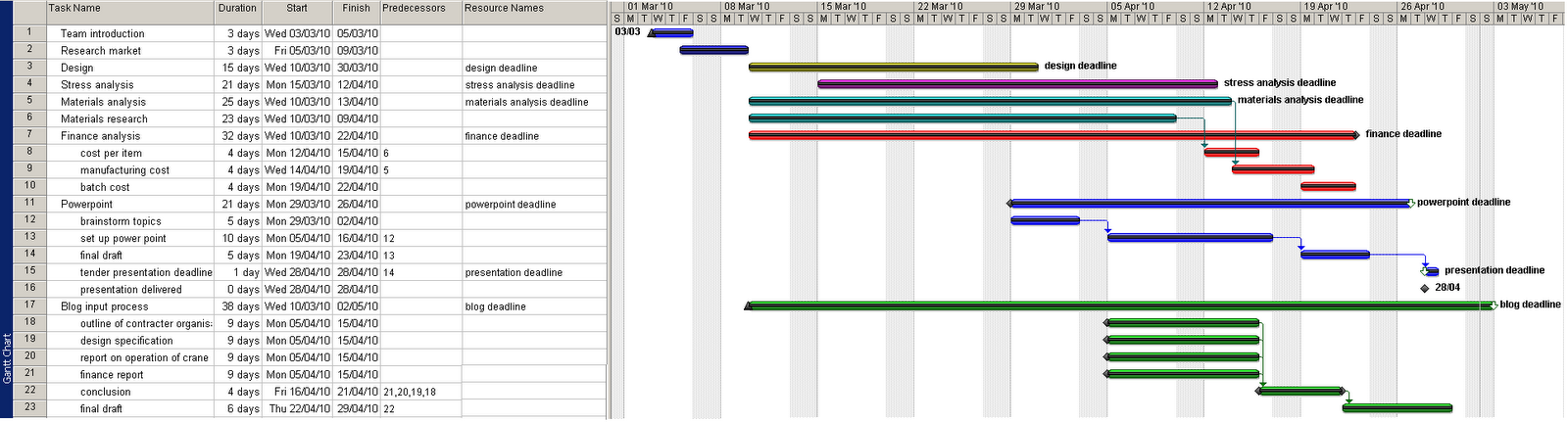
Final Chart
The following action plan was produced to take into consideration the new deadlines for the final project, the Easter holidays which caused communication issues between some team members and the time delay caused by the unexpected review of the stress analysis which obtained the final design (according to BS standards).
The tasks below show the project has been complete and to a great extent followed the new guidelines in order to avoid overrunning and missing deadlines.

The tasks below show the project has been complete and to a great extent followed the new guidelines in order to avoid overrunning and missing deadlines.

Friday, 30 April 2010
Cheif Designers Project Review
I believe this project went well and that we worked well as a team. We remained on schedule for the first stage and , due to continuous work from the group over the Easter holidays, were able to complete the project on time despite some set backs.
The greatest problem we faced was that two of our group members were missing for approximately three weeks each at different stages of the project. Our materials specialist was absent due to illness at the start of the project, and our stress analyst was not contactable over the Easter holidays due to a breakdown in communication. The remaining group members however worked well around these losses and those who did miss part of the project worked hard upon their return to make up for their loss, in order to produce the final crane to a high standard.
The second set back occurred towards the start of the Easter break when it was realised that the main beam needed redesigning. This set us back about a week, though did give us the opportunity to redesign the beam to British standard dimensions.
The greatest flaw in the design that was picked up in the Q&A section of the presentation was that the beam, at 5.5 metres in length, was on the border of being impractically large. This was a problem that we had considered, though splitting the beam would have weakened it significantly. If I had more time for this project , I would spend much of it considering possible solutions to splitting the beam. In addition, the design of the head piece of the shoulder component would be difficult to manufacture for a reasonable cost.
In conclusion, though we had a few issues, I believe this project was a success, and that we completed it to a high standard as well as to specification.
Thursday, 29 April 2010
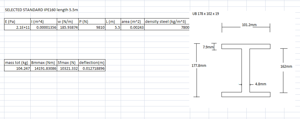
Final dimension sizes for I beam
Exploded crane animation
This is the animation describing the assembly of the crane.
The colour scheme is arbitrary in this video, designed to allow the viewer to differentiate easily between components.
Safety - Tools
It is highly advisable to tighten the U-bolts by hand with a spanner rather than with a torsion torsion wench. It is also advisable to use a spirit level to ensure that the beam is horizontal before loading the crane to minimise the chances of the hoist slipping along the beam.
Tuesday, 27 April 2010
Revised Calculations
From the analysis done to work out how much length was needed for an object to move 4m maximum from one point to another it was calculated that the beam would have to be a minimum standard length of 5.5m
Revising the calculations done at an earlier date a delfection of 12.29mm was established with the same CSA.
Revising the calculations done at an earlier date a delfection of 12.29mm was established with the same CSA.
Sunday, 25 April 2010
Company Name and Logo
The company name chosen was Dynamic Engineering Solutions (DES). This name is both memorable and slightly amusing, though the comical effect wears off the more one hears it thus allowing are clients to take our company seriously once the initial attention catching humour wears off. The logo chosen utilises primary colours in order to grab attention in an aesthetically pleasing manor. The image below shows the logo for official correspondence.

 The final orientation of the company logo is the squared off version design to be placed on CAD drawings and on our products. This logo, depicted below, is both bold and instantly recognisable. It is designed so that perspective clients will be attracted to our company when they see it in the field.
The company motto will be added to this design for our advertising. The motto required a short, memorable, and to-the-point sentence to sum up our companies values, and inspire the trust of our perspective clients.
The motto chosen was "just ask DES", which was designed to imply that we shall go above and beyond to satisfy our clients needs whatever they may be. The image below depicts the company logo with the motto attached.
The final orientation of the company logo is the squared off version design to be placed on CAD drawings and on our products. This logo, depicted below, is both bold and instantly recognisable. It is designed so that perspective clients will be attracted to our company when they see it in the field.
Saturday, 24 April 2010
Formal Engineering Drawings Templates
The follow image is the engineering drawing template for the crane components. The company logo is yet to be inserted, but all other elements are as they will be in the formal proposal.
 The next image is of the engineering drawing template for the crane assemblies, one will be standard and the other one will be exploded.
 This drawing template also requires the company logo, though is also otherwise as the final assembly drawings will be presented.
The blue text represents links to the part designs, which will be automatically replaced with the appropriate information.
The next image is of the engineering drawing template for the crane assemblies, one will be standard and the other one will be exploded.This drawing template also requires the company logo, though is also otherwise as the final assembly drawings will be presented.The blue text represents links to the part designs, which will be automatically replaced with the appropriate information.
Thursday, 22 April 2010
Buckling calculations for the legs, foot extender and crane shoulder corrected
recently went over some of my old calculations for the legs and realised i had used the wrong Euler formula for the crane shoulder legs and foot extender. Here are my corrected calculations.
P.S these calculations do not imply that any changes should be made to the crane, material or design wise. I simply wanted to correct my mistakes.


Presentation

Machining Cost
One of the questions that needs to be answered is how much it is going to cos to make the crane. The beam is of a standard design and can be purchased pre-made and cut to the required length. However the legs must be specially made and a machining cost must be evaluated.
First and foremost we must look at the different types of tools that could be used to cut the aluminium into the specified dimensions.
High Speed Steel
This material was invented in the 19th century and was a massive improvement on the standard cutting tools of that time since they can function under higher speeds and hotter temperatures than standard steel tools. Out of all the tools researched this has the lowest range of cutting speeds, however it is still able to cut aluminium to a rough finish, but the life of the tool is significantly small when cutting this material. However the material is the cheapest type of tools looked at.
Cast Alloys
This material is a standard base metal (e.g. iron) which has been augmented with an alloying element (e.g. nickel, tungsten, chromium etc.). The reason for doing this is to improve the metals strength and reaction to heat. This group of cutting tools can operate at higher cutting speeds and temperatures than High Speed Steel, and the tool life is significantly higher. The price of these tools are also quite reasonable.
Carbides
Strong metal such as titanium are part of the this group of materials, and are used in some of the most extreme situations, for example they are used to construct the fuselage of space shuttles which are put under the most extreme temperature any material could be put through. In relation to cutting tools, this material is second only to certain ceramics in cutting speed and operating temperatures. The pieces are highly expensive though.
Price for Cast Alloy cutting tools = approx £20.00 (set of 11 cutting tools)
source: axminster tool centre
Ceramics
As mentioned before this the type of cutting tool that is second to none. Ceramic is the name given to most crystalline oxide structures, such as silicon carbide, saolin, titanium carbide. The strength of this material has been proven through the use in space shuttle re-entry shields, military ballistic vests, and heavy duty abrasives. Yet, as said with the carbides ceramics are very expensive to produce so the tool prices are very dear, but the tool life balances that out quite well.
By looking at this research it can be said that for the current project using Cast Alloy tools would be the most beneficial to the production of the cranes.
area of aluminium = 1.88 m^2
cutting speed = 1.1-1.8 m/sec (66-108 m/min)
life of cutting tool when cutting to a finished result = approx 175 mins
cost per cutting tool = £20/11 = £1.82 per tool
tool cost = £1.8/175mins = £0.01/min
minimum wage of machine operator = £6/per hour = £0.1/min
Machining Cost = Co x tm
Co = operator wage + overhead
overhead = life of tool + material able to be cut by tool per minute
tm = amount of time needed for task to be completed
Machining Cost = £241 per/min
This is quite a reasonable cost seing as the amount of material that can be machined within a minute will make up multiple kits.
source of calculations: Handbook of Material Selection, Myek Kutz, 2002 edition, published by John Wiley & Sons New York.
other sources:
market prices for several cranes
The following lists some of the available cranes on the market (curtesy of www.amazon.com), in order to assist the finance officer with rough prices we are likely to be selling our crane for:


Manufacturing costs
Manufacturing Cost
According to 'Swift, K.G. & Booker, J.D. , Process selection: From design to manufacture', the Manufacturing cost = material cost + processing cost.
This can be spit up further, processing cost consisting of basic processing cost multiplied by the relative cost coefficient. Hence the new equation will be: Manufacturing cost = material cost + (Basic Processing cost*Relative Cost Coefficient).
Relative Cost Coefficient
The equation for the Relative Cost Coefficient is : Rc = Cmp.Cc.Cs.Ctf, where:
The 'Cmp' is dependant on the process used to manufacture and can be found from the 'From design to manufacture' book.
Hence the new equation will be Manufacturing cost = material cost + (Basic Processing cost*(Cmp.Cc.Cs.Ctf))
References:
'Swift, K.G. & Booker, J.D. , Process selection: From design to manufacture'.
According to 'Swift, K.G. & Booker, J.D. , Process selection: From design to manufacture', the Manufacturing cost = material cost + processing cost.
This can be spit up further, processing cost consisting of basic processing cost multiplied by the relative cost coefficient. Hence the new equation will be: Manufacturing cost = material cost + (Basic Processing cost*Relative Cost Coefficient).
Relative Cost Coefficient
The equation for the Relative Cost Coefficient is : Rc = Cmp.Cc.Cs.Ctf, where:
'Cmp' is the material process suitability
'Cc' is the component geometry
'Cs' is the size, thickness consideration
'Ctf' is the tolerance/surface finish
All of these unknowns should already be held available by the design team except for the 'Cmp'.'Cc' is the component geometry
'Cs' is the size, thickness consideration
'Ctf' is the tolerance/surface finish
The 'Cmp' is dependant on the process used to manufacture and can be found from the 'From design to manufacture' book.
Hence the new equation will be Manufacturing cost = material cost + (Basic Processing cost*(Cmp.Cc.Cs.Ctf))
References:
'Swift, K.G. & Booker, J.D. , Process selection: From design to manufacture'.
Wednesday, 21 April 2010
Beam Length Analysis
The beam length is determined on a few conditions and they are:
- The position of the struts at the base of the leg
- The dimensions of the object to be lifted
1/
The struts position is fixed in relation to the beam so therefore
length of leg at full extension = 1.145m
angle leg sits at = 30 degrees
s.t.f:
1.145 x sin 30 = 0.5725m
however the position of the leg in relation to the object is not that simple. Each leg is 120 degrees from each other and two of the legs sit 30 degrees from the plane which runs parallel with the leg itself.
s.t.f
0.5725 x sin 30 = 0.28625m = 286.25mm
2/
The dimensions of the material is not as big a problem as it would seem, because if we for example take the material to be of a cuboid nature (like in the load dimensions calculated) then if the worst case scenario set is that the material is 4.16m long then we can just work at a different angle by position the crane so we work on a plane with gives more room for the object to moved. However if we come upon a scenario where the material is the same distance no matter what way you take it, for example circular.
The volume of the worst case scenario = 0.3744m^3
s.t.f
pi x r^2 x l = 0.3744m^3
in the previous examples l = 450mm so it will be used in these calculations.
s.t.f
r = 0.515m
So from these two calculated results we can say that if the load has to be moved 4m then the length of the beam must be:
4m + 0.515m + (2 x 0.28625m) = 5.0875m
The beam has also got to have an extra 0.290m added to this length since it must sit in the shoulders. So therefore the overall minimum length needed is 5.3775m
With this it can be deduced that we need to use the standard length of 5.5m for the beam so that in the worst case scenario picking up the most common material.
With this it can be deduced that we need to use the standard length of 5.5m for the beam so that in the worst case scenario picking up the most common material.
Types of Transport
The kit is needed to be transported to the disaster site so there is a few criteria that needs to be fulfilled if it is to perform the task required.


- It must be able to carry the entire crane kit (including the beam)
- It must be able to carry all four people to the site
- It must be able to traverse very rough terrain
- It must be able to reach every site that the crane is needed in case the crane needs to be transported over long distances.
Car
They are widely used and comes in a variety of shapes and sizes. If the vehicle is of the right design then it can carry all the people required and should be able to traverse the environment with ease, especially if it has 4 wheel drive. Since most cars that would be chosen for this are of a moderate size and are quite nimble they should be able to reach most of the scenarios that it might come up against. The only drawback is that the internal storage space may not be sufficient to store the kit. The kit can be strapped to the top of the care but then there would be risk of damage since it is not protected by the vehicle.
Hovercraft
Hovercraft were designed so as all terrain vehicles; this is because the only thing between the vehicle and the ground is air so there is nothing it cannot traverse. The storage space and number of people which can be transported is dependant on the size and they range of single seated to ferry sized. The only downside to these vehicles is if the skirt of the hovercraft is damaged or one of the props powering the hover propellers is damaged then the vehicle would be useless and would take awhile to repair.
Van/Truck
Both modes of transport are big enough to store and transport the kit to wherever it needs, and both have sufficient engine power. The passenger space in both is not as could as the cars, however it would suffice. The only difference between the two is that in most cases the clearance between the ground and the chassis of the van is not a lot and may cause the vehicle to beach on a protruding bit of ground. The truck however has sufficient clearance and can reach most situations without duress.

Looking at the pros and cons of each mode of transport, the only one that full fills all the necessary requirements is the truck. So therefore the most obvious vehicle that should be encouraged to be used is such.
Beam Restrictions
It was brought up that since the beam could not be laid flat in the bed of a pick up truck the component should be split into sections and then packed with the rest in the kit. A few options were brought up, for example:
Joints Attachments


If the beam was cut into sections it would basically be put back together with joint attachments and screws and bolts. It would restrict the beam from rotating or pivoting in an unnatural manner and it would be easy to assemble and disassemble. The image below is a rough interpretation of the idea put foward.
Pinned Joints
Probably the simplest idea that was produced. The beam could be split into sections and a male/female connection be cut into each section. Then each joint could be held together by a simple bolt and nut. This idea would be the quickest and most efficient way of splitting the beam. The idea does have flaws, one being that the restraints on the joint do not prevent the pieces from pivoting.
These ideas however all have one thing in common and that is that they will drastically increase the beams chances of failing. This is due to a phenomenon known as Stress Concentration.
Stick Welding
This is the strongest idea produced. If the beam was to transported to the event and when it is to be used, each part is welded together. When the beam is needed somewhere else the beam does not need to be separated again so it can be carried as a whole piece. This does however mean that a stick welding kit would be needed when the crane is being used and someone qualified would have to construct it, but stick welding is one of the quickest and simplest welding procedures it should not take too long to assemble.

All these ideas however have one thing in common, they would all increase the chances of failure massively. This is because of a phenomenon known as Stress concentration.
Stress Concentration
Definition: (mechanics) A condition in which a stress distribution has high localized stresses; usually induced by an abrupt change in the shape of a member; in the vicinity of notches, holes, changes in diameter of a shaft, and so forth, maximum stress is several times greater than where there is no geometrical discontinuity.

If the beam was to be put into sections discontinuities in the geometry would have to be created and as stated would greatly increase the force applied to that point.
The Stress Concentration is measured as the Stress Concentration factor which is either calculated through theoretical methods or by using finite element methods. It calculates the stress along the axis of the discontinuity with stress applied on that point. The factor is a function of the geometry of the discontinuity and not the size, which means it does not matter how big it is, but of what shape it is.
Winch Impairment
Another issue that will arise is the track on which the winch will run will be distorted. This will either restrict or slow down the functioning of the crane, which in turn causes the crane to be unsafe and unreliable.
An example is a simple hole through a sample cause the force lines to distort in the manner shown below.

So in conclusion it would not be plausible to make the beam in sections to be put together otherwise it would undermine the quality of the crane, the safety of the people working with it and general sales of the product. The beams strength is dependant on it being one complete object
Transport Research
Probably the most common and most useful vehicles to use in an environment affected by a natural disaster would be a type of 4x4 pick up truck. However there are many different types to choose from.


Compact Pick up Trucks
This is the most common type of pick up truck on the marked, being that is the original type from when the design was first invented in the 60's. As it says in it's name the vehicle compact so it will be able to fit into situations that normal trucks wouldn't. However the bed is quite small and the cab only holds two people, however the other two people needed on the crane can sit in the bed anyhow.
Ford Ranger XLT 2009
Full-Size Pick up Trucks
This type of truck is designed to carry heavy loads and carry it over rough terrain. Most standard trucks of this nature can carry up to 450kg in the bed, and others can carry up to six times as much as that. The bed is usually designed to be around 1.2m x 2.4m in area. With rear wheel drive and 4 wheel drive as an optional, this truck can handle most terrain, especially if it is powered by a v10 engine. The largest type of this pick up truck are called "duallies" since they have 4 rear wheels, two on each side with an axle between. This would suit the requirements needed however the vehicle might be too cumbersome, and could get trapped in a tight squeeze.

Ford F-150 2007-2008 (extended)
Mid-Size Pick Up Trucks
This is the all rounder of the family. It has the advantages of being smaller than a full-size pick up truck and can carry the same load as one. It also has the option of having the bed in a longer, and wider style, the Toyota show has can come with a long bed 1.87m by 1.44m. The original models of these did not have the engine power needed to traverse extreme conditions, for example in an earthquake zone, however the newer models like the Toyota shown can come with a V6 engine. They have even more durability since they can also come with a double cab, which allows all four people to sit within the cab and not risk sitting in the bed with the gear.

Toyota Tacoma TRD 2001-2004 (extended cab)
Sports Utility Trucks (SUT)
The SUT is a cross breed between a Full-size pick up truck and a SUV (Sports Utility Vehicle). Where the cab is quite large so it can fit more people (up to 6 passengers) but it has a bed on the back designed for light or heavy loading. It would be very useful, however the design is a bit too much for what it is needed for and much would go to waste.

Dodge Ram 1500 crew cab
I believe looking at the choices the Mid-Size pick up truck is the best choices since it is the most adaptable out of all of them and even thought the bed is not as long as the full-size pick up it will suffice and it will be able to go into situations that it's larger brethren would not.
Sunday, 18 April 2010
approximate prices for crane materials
Aluminium alloys
According to London Market Exchange figures on http://www.metalprices.com/ the averegae price of an alluminium alloy is 1 us dollar/ pound. Using this info and my estimates on the mass of the legs iv calculated that the approximte cost of the legs.
mass of both legs = 27.4 kg = 60.28 lb
cost = $60-$61 = £40
Carbon steel
The LME doesn't give a specific price for carbon steel (at least i couldn't find one) however its most recent price on steels in general was £350 per tonne. however http://www.meps.co.uk/ has a specific prices for carbon steels that are used to build beams but the prices are 4 months old. As meps gives a specified price i will use this to calculate the price of the boom.
mass of ub178 boom = 94.77 kg
cost of carbon steel = $691 per tonne
cost of boom = $65.5 = £42.55
The prices used are bulk purchase prices, individually the boom and the legs may cost more. Also these prices dont take into consideration the cost of manufacturing the boom and the legs.
Sectioned Beams
According to BS 5950-12000 part 1 it is also possible to carry out the following design in order to split the beam into several sections:

This would create several issues including stress concentrations and movement hindrance of trolley, as there is only a small clearance available between the trolley and the beam in order to allow successful and controlled movement.


This would create several issues including stress concentrations and movement hindrance of trolley, as there is only a small clearance available between the trolley and the beam in order to allow successful and controlled movement.


Saturday, 17 April 2010


Load dimensions
To obtain an approximate maximum length for the glide beam the 4m travelling distance needs to be taken account of along with any other clearances for load and shoulder joints total approx 290mm.

For the worst case scenarios of loading conditions, the two most probable loads (rubble) include reinforced concrete and steel I beams.
Using the BS 5950 standards, [Limit State Design of Reinforced Concrete By B. C. Punmia, Arun Kumar Jain, Arun Kr. Jain, Ashok Kr. Jain] to find common dimension sized beams e.g.

Approximate steel: concrete ratio would need to be estimated to calculate volumes, and the missing Z dimension. Based on several different pre-stressed processes, wire dimensions...
Processes from [Limit State Design of Reinforced Concrete By B. C. Punmia, Arun Kumar Jain, Arun Kr. Jain, Ashok Kr. Jain]:


Approximate dimensions sizes were hence obtained:

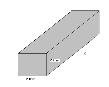
The final ‘z’ dimension would need to be calculated. The following parameters are taken into account:

Calculations of dimensions to give a load of approximately 1 tonne:
Steel
5% of the cross sectional area =0.0045m^2
Assume Z=4m to obtain volume for the following equation:
Mass = Volume * Density
Mass= (0.0045*4)m^3*(7800) kg/m^3
Mass=140.4kg
Concrete
95% of the cross sectional area=0.0855m^2
Assume Z=4m to obtain volume for the following equation:
Mass = Volume * Density
Mass= (0.0855m *4)m^3*(2400) kg/m^3
Mass=820.8kg
Total mass = 140.4kg + 820.8kg= 961.2kg
In order to obtain the desired mass approximately a 4% increase in length would be required, hence obtaining:
Steel
5% of the cross sectional area =0.0045m^2
Assume Z=4.16m to obtain volume for the following equation:
Mass = Volume * Density
Mass= (0.0045*4.16)m^3*(7800) kg/m^3
Mass=146.016kg
Concrete
95% of the cross sectional area=0.0855m^2
Assume Z=4.16m to obtain volume for the following equation:
Mass = Volume * Density
Mass= (0.0855m *4.16)m^3*(2400) kg/m^3
Mass=853.632kg
Total mass = 146.016kg + 853.632kg = 999.648kg
Hence the length Z required of the load that would need to be lifted is approx 4.16m.
Another possibility is to find several shorter sections and hoist them together or one wider section with the following dimensions:

Z would be approximately 2m.
Steel I beams
The following data was obtained from http://www.engineeringtoolbox.com/british-universal-steel-columns-beams-d_1316.html:

A standard I beam was selected for the worst scenario load that could be found and require lifting (this particular beam was selected as it poses the greatest load risk as it could potentially surpass the 1 tonne requirement)
Calculate Z length
1000kg/238.1 kg/m = 4.19m (length that would need to be found to pose issues to the crane)
From these calculations a total clearance of approximately 300 -400mm may be required to be able to lift most available loads safely from a to b.
It will be assumed that these loads will be lifted from their midsection (centre of gravity) to maintain safety.

Another issue which would need to be addressed is the following:


For the worst case scenarios of loading conditions, the two most probable loads (rubble) include reinforced concrete and steel I beams.
Using the BS 5950 standards, [Limit State Design of Reinforced Concrete By B. C. Punmia, Arun Kumar Jain, Arun Kr. Jain, Ashok Kr. Jain] to find common dimension sized beams e.g.

Approximate steel: concrete ratio would need to be estimated to calculate volumes, and the missing Z dimension. Based on several different pre-stressed processes, wire dimensions...
Processes from [Limit State Design of Reinforced Concrete By B. C. Punmia, Arun Kumar Jain, Arun Kr. Jain, Ashok Kr. Jain]:


Approximate dimensions sizes were hence obtained:
The final ‘z’ dimension would need to be calculated. The following parameters are taken into account:

Calculations of dimensions to give a load of approximately 1 tonne:
Steel
5% of the cross sectional area =0.0045m^2
Assume Z=4m to obtain volume for the following equation:
Mass = Volume * Density
Mass= (0.0045*4)m^3*(7800) kg/m^3
Mass=140.4kg
Concrete
95% of the cross sectional area=0.0855m^2
Assume Z=4m to obtain volume for the following equation:
Mass = Volume * Density
Mass= (0.0855m *4)m^3*(2400) kg/m^3
Mass=820.8kg
Total mass = 140.4kg + 820.8kg= 961.2kg
In order to obtain the desired mass approximately a 4% increase in length would be required, hence obtaining:
Steel
5% of the cross sectional area =0.0045m^2
Assume Z=4.16m to obtain volume for the following equation:
Mass = Volume * Density
Mass= (0.0045*4.16)m^3*(7800) kg/m^3
Mass=146.016kg
Concrete
95% of the cross sectional area=0.0855m^2
Assume Z=4.16m to obtain volume for the following equation:
Mass = Volume * Density
Mass= (0.0855m *4.16)m^3*(2400) kg/m^3
Mass=853.632kg
Total mass = 146.016kg + 853.632kg = 999.648kg
Hence the length Z required of the load that would need to be lifted is approx 4.16m.
Another possibility is to find several shorter sections and hoist them together or one wider section with the following dimensions:

Z would be approximately 2m.
Steel I beams
The following data was obtained from http://www.engineeringtoolbox.com/british-universal-steel-columns-beams-d_1316.html:

A standard I beam was selected for the worst scenario load that could be found and require lifting (this particular beam was selected as it poses the greatest load risk as it could potentially surpass the 1 tonne requirement)
Calculate Z length
1000kg/238.1 kg/m = 4.19m (length that would need to be found to pose issues to the crane)
From these calculations a total clearance of approximately 300 -400mm may be required to be able to lift most available loads safely from a to b.
It will be assumed that these loads will be lifted from their midsection (centre of gravity) to maintain safety.

Another issue which would need to be addressed is the following:

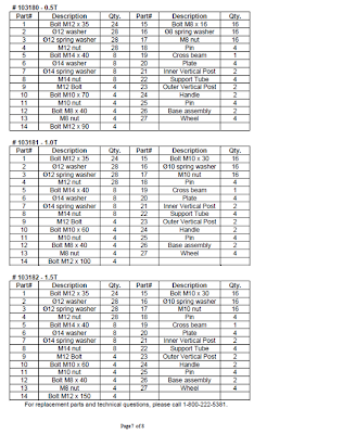
Template for individual pages
The following documents found on [http://www.northerntool.com/downloads/manuals/103181.pdf] and BushmanAvonTec would be useful as templates for our project i.e. the individual page sections, due to their quality and professional layouts.
Sections to include in the following pages:
Overall design of crane components
• Outlining the overall design of the crane components
• Details drawings of each component
Construction of crane using the kit of parts
• Exploded view (use for reference to where each part from the kit fits)
• Fitness for purpose of each part
• Assembly
• Maintenance
• Safety
Finance and costs of each kit
• breakdown of the cost of each kit
• contract cost for 100 cranes
• Commercial costs for primarily government bodies (opportunity)
• Licensing kits to third parties (opportunity)
The purpose for the following two documents are to be used by the materials specialist and the stress analyst as a template in order to complete section "Section 3 - Construction of crane using the kit of parts":
Document 1


Points to take away from document 1:
Document 2


Points to take away from document 2:
Sections to include in the following pages:
Overall design of crane components
• Outlining the overall design of the crane components
• Details drawings of each component
Construction of crane using the kit of parts
• Exploded view (use for reference to where each part from the kit fits)
• Fitness for purpose of each part
• Assembly
• Maintenance
• Safety
Finance and costs of each kit
• breakdown of the cost of each kit
• contract cost for 100 cranes
• Commercial costs for primarily government bodies (opportunity)
• Licensing kits to third parties (opportunity)
The purpose for the following two documents are to be used by the materials specialist and the stress analyst as a template in order to complete section "Section 3 - Construction of crane using the kit of parts":
Document 1


Points to take away from document 1:
- use a manual type format
- include diagrams with warnings to the user for general issues with putting together the crane, safety... and can use different colours (i.e red) to put emphasis on the importance of the text.
- Logo
- Assembly instructions
- Operating instructions
- Loading capacity
- Any extra tools required for assembly
Document 2


Points to take away from document 2:
- Provide a table with a list of components and refer the location of each part of the crane by using a labelled exploded view diagram
- Notes on crane maintenance
- Notes on operation
- Personal safety notes and workspace safety
- Warning labels
Subscribe to:
Posts (Atom)