Courtesy of:
Mechanics of engineering materials, second edition, by PP Benham, RJ Crawford & CG Armstrong;
Elements of Strength of Materials, International Student Edition, by S Timoshenko;
In order to obtain the following equations in the calculations:

A formula sheet from "Elements of Strength of Materials, International Student Edition, by S Timoshenko" where by the principle of superposition two factors (deflection due to a uniformly distributed load and deflection due to a point load) were combined providing the final deflection value.

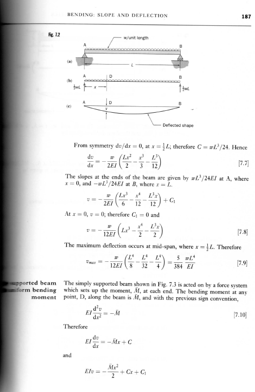
The theory of superposition is explained in the following paragraphs along with the diagrams provide a visual image of how the beam will behave when subjected to varying loads (this is an important situation as it's behaviours in the following example are very similar to the behaviours we could expect our crane to experience):


The following scans are proofs of the formula obtained for the varying deflection loads and can be used as a template for our mathematical equations (for double checking values or if an error was made in the final value where could it have occurred by following the template).
For a point load our calculations would need to follow the following format:


For a uniformly distributed load the calculations would need to follow the following format:

For the particular type of I beam our crane will be using, due to the shape we have selected, it was required to use the following formula for is second moment of area.

However in order to find the maximum bending moment and the maximum shear force the following diagrams were used along with the knowledge that maximum bending moment will occur when the 1000kg load is placed in the middle of the beam and that the max shear force when the load is placed at its ends:


the diagrams and calculations allowed through the theory of superposition to combine:
for max shear:
Pa/l (for point load where a=l)+ wl/2 (uniform load)
therefore obtaining the equation: wl/2 + P
for max BM:
(Pab)/l (for point load where a=l/2 and b=l/2) + (wl^2)/8
Therefore obtaining the equation: (wl^2)/8 +Pl/4
The final thing which would need to be calculated is the max BM and SF that the particular beam we have selected can handle due to its dimensions and type of structural steel component. ( if these values are higher than the ones obtained for the calculations that our beam will create with its load, it will mean the beam is safe to use under these conditions as it will not fail under them):


the following equations will be used:
M = Z ("fy") where Z = I/y (for the moment)
V= "dw""tw"("fy"/(3)^(1/2))
"fy"= specific design strength of the steel selected from a list of steel grades (e.g. are given on previous blogs)
Another factor that could be calculated in its stead includes the working stress at a distance point y. It would need to be found using the yield point or ultimate tensile stress for that particular grade of steel and divide it by a safety factor e.g. 2 (as given in the example). This will ensure that the steel will remain in the safe elastic region and avoid becoming permanently deformed.
No comments:
Post a Comment