This module has been well informative and allowed the group to successfully design a crane to fit a given brief, in accordance to BS standards.
It was important to choose the most suitable crane design from the large variety found in the first week: gantry, jib, tower crane, bridge crane, stacker crane... Ultimately after a long debate, the group chose a gantry type as it best suited the scenario and had the best chances of working productively in accordance to the brief.
Calculations, materials and costs were continuously assessed and reviewed by each member of the group to ensure faults were quickly located and the final design could be altered accordingly.
The main issues brought up during the presentation were:
• Beam length (5.5m) which was noticeably long, but the team had originally accounted for this situation and researched into alternative scenarios including splitting of the beam into several sections. This was found to be impractical, costly, time consuming and would increase stresses, shear and bending forces which the beam would experience (increasing safety issues).
• Shoulder head would be more costly than calculated due to its unique design
Overall the group worked effectively for most of the duration of the project and despite a couple of setbacks, quickly produced action plans in order to assess the situation, compensate and work efficiently to finish the crane and avoid missing the deadlines.
A troubling issue, which was ultimately resolved, was the lack of communication between two members and the rest of the group at various intervals of the project. This included the first 3 weeks where the materials specialist was absent as a result of illness but had not informed the team during this time in order to allow the rest to compensate and to send information regarding progress. The other occurred when it was not possible to contact the stress analyst during the time of the Easter Holiday in order to inform of the issues found with the initial set of calculations for the I beam.
Showing posts with label Sandra Donohoe. Show all posts
Showing posts with label Sandra Donohoe. Show all posts
Sunday, 2 May 2010

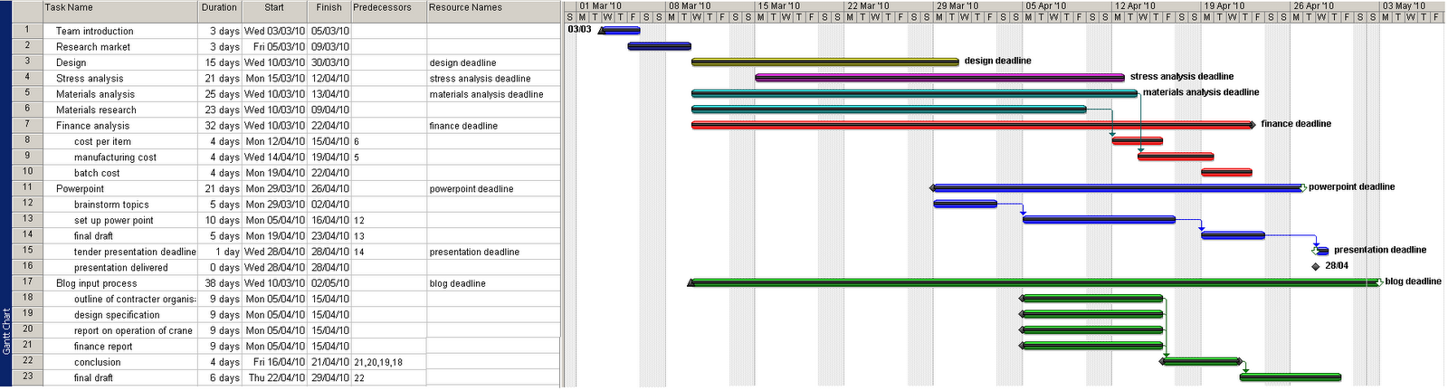
Final Chart
The following action plan was produced to take into consideration the new deadlines for the final project, the Easter holidays which caused communication issues between some team members and the time delay caused by the unexpected review of the stress analysis which obtained the final design (according to BS standards).
The tasks below show the project has been complete and to a great extent followed the new guidelines in order to avoid overrunning and missing deadlines.

The tasks below show the project has been complete and to a great extent followed the new guidelines in order to avoid overrunning and missing deadlines.

Thursday, 29 April 2010
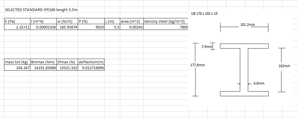
Final dimension sizes for I beam

Thursday, 22 April 2010
market prices for several cranes
The following lists some of the available cranes on the market (curtesy of www.amazon.com), in order to assist the finance officer with rough prices we are likely to be selling our crane for:


Sunday, 18 April 2010
Sectioned Beams
According to BS 5950-12000 part 1 it is also possible to carry out the following design in order to split the beam into several sections:

This would create several issues including stress concentrations and movement hindrance of trolley, as there is only a small clearance available between the trolley and the beam in order to allow successful and controlled movement.


This would create several issues including stress concentrations and movement hindrance of trolley, as there is only a small clearance available between the trolley and the beam in order to allow successful and controlled movement.

Saturday, 17 April 2010
Load dimensions
To obtain an approximate maximum length for the glide beam the 4m travelling distance needs to be taken account of along with any other clearances for load and shoulder joints total approx 290mm.

For the worst case scenarios of loading conditions, the two most probable loads (rubble) include reinforced concrete and steel I beams.
Using the BS 5950 standards, [Limit State Design of Reinforced Concrete By B. C. Punmia, Arun Kumar Jain, Arun Kr. Jain, Ashok Kr. Jain] to find common dimension sized beams e.g.

Approximate steel: concrete ratio would need to be estimated to calculate volumes, and the missing Z dimension. Based on several different pre-stressed processes, wire dimensions...
Processes from [Limit State Design of Reinforced Concrete By B. C. Punmia, Arun Kumar Jain, Arun Kr. Jain, Ashok Kr. Jain]:


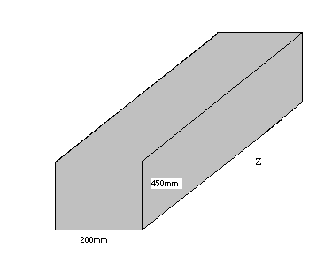
Approximate dimensions sizes were hence obtained:

The final ‘z’ dimension would need to be calculated. The following parameters are taken into account:

Calculations of dimensions to give a load of approximately 1 tonne:
Steel
5% of the cross sectional area =0.0045m^2
Assume Z=4m to obtain volume for the following equation:
Mass = Volume * Density
Mass= (0.0045*4)m^3*(7800) kg/m^3
Mass=140.4kg
Concrete
95% of the cross sectional area=0.0855m^2
Assume Z=4m to obtain volume for the following equation:
Mass = Volume * Density
Mass= (0.0855m *4)m^3*(2400) kg/m^3
Mass=820.8kg
Total mass = 140.4kg + 820.8kg= 961.2kg
In order to obtain the desired mass approximately a 4% increase in length would be required, hence obtaining:
Steel
5% of the cross sectional area =0.0045m^2
Assume Z=4.16m to obtain volume for the following equation:
Mass = Volume * Density
Mass= (0.0045*4.16)m^3*(7800) kg/m^3
Mass=146.016kg
Concrete
95% of the cross sectional area=0.0855m^2
Assume Z=4.16m to obtain volume for the following equation:
Mass = Volume * Density
Mass= (0.0855m *4.16)m^3*(2400) kg/m^3
Mass=853.632kg
Total mass = 146.016kg + 853.632kg = 999.648kg
Hence the length Z required of the load that would need to be lifted is approx 4.16m.
Another possibility is to find several shorter sections and hoist them together or one wider section with the following dimensions:

Z would be approximately 2m.
Steel I beams
The following data was obtained from http://www.engineeringtoolbox.com/british-universal-steel-columns-beams-d_1316.html:

A standard I beam was selected for the worst scenario load that could be found and require lifting (this particular beam was selected as it poses the greatest load risk as it could potentially surpass the 1 tonne requirement)
Calculate Z length
1000kg/238.1 kg/m = 4.19m (length that would need to be found to pose issues to the crane)
From these calculations a total clearance of approximately 300 -400mm may be required to be able to lift most available loads safely from a to b.
It will be assumed that these loads will be lifted from their midsection (centre of gravity) to maintain safety.

Another issue which would need to be addressed is the following:


For the worst case scenarios of loading conditions, the two most probable loads (rubble) include reinforced concrete and steel I beams.
Using the BS 5950 standards, [Limit State Design of Reinforced Concrete By B. C. Punmia, Arun Kumar Jain, Arun Kr. Jain, Ashok Kr. Jain] to find common dimension sized beams e.g.

Approximate steel: concrete ratio would need to be estimated to calculate volumes, and the missing Z dimension. Based on several different pre-stressed processes, wire dimensions...
Processes from [Limit State Design of Reinforced Concrete By B. C. Punmia, Arun Kumar Jain, Arun Kr. Jain, Ashok Kr. Jain]:


Approximate dimensions sizes were hence obtained:
The final ‘z’ dimension would need to be calculated. The following parameters are taken into account:

Calculations of dimensions to give a load of approximately 1 tonne:
Steel
5% of the cross sectional area =0.0045m^2
Assume Z=4m to obtain volume for the following equation:
Mass = Volume * Density
Mass= (0.0045*4)m^3*(7800) kg/m^3
Mass=140.4kg
Concrete
95% of the cross sectional area=0.0855m^2
Assume Z=4m to obtain volume for the following equation:
Mass = Volume * Density
Mass= (0.0855m *4)m^3*(2400) kg/m^3
Mass=820.8kg
Total mass = 140.4kg + 820.8kg= 961.2kg
In order to obtain the desired mass approximately a 4% increase in length would be required, hence obtaining:
Steel
5% of the cross sectional area =0.0045m^2
Assume Z=4.16m to obtain volume for the following equation:
Mass = Volume * Density
Mass= (0.0045*4.16)m^3*(7800) kg/m^3
Mass=146.016kg
Concrete
95% of the cross sectional area=0.0855m^2
Assume Z=4.16m to obtain volume for the following equation:
Mass = Volume * Density
Mass= (0.0855m *4.16)m^3*(2400) kg/m^3
Mass=853.632kg
Total mass = 146.016kg + 853.632kg = 999.648kg
Hence the length Z required of the load that would need to be lifted is approx 4.16m.
Another possibility is to find several shorter sections and hoist them together or one wider section with the following dimensions:

Z would be approximately 2m.
Steel I beams
The following data was obtained from http://www.engineeringtoolbox.com/british-universal-steel-columns-beams-d_1316.html:

A standard I beam was selected for the worst scenario load that could be found and require lifting (this particular beam was selected as it poses the greatest load risk as it could potentially surpass the 1 tonne requirement)
Calculate Z length
1000kg/238.1 kg/m = 4.19m (length that would need to be found to pose issues to the crane)
From these calculations a total clearance of approximately 300 -400mm may be required to be able to lift most available loads safely from a to b.
It will be assumed that these loads will be lifted from their midsection (centre of gravity) to maintain safety.

Another issue which would need to be addressed is the following:

Template for individual pages
The following documents found on [http://www.northerntool.com/downloads/manuals/103181.pdf] and BushmanAvonTec would be useful as templates for our project i.e. the individual page sections, due to their quality and professional layouts.
Sections to include in the following pages:
Overall design of crane components
• Outlining the overall design of the crane components
• Details drawings of each component
Construction of crane using the kit of parts
• Exploded view (use for reference to where each part from the kit fits)
• Fitness for purpose of each part
• Assembly
• Maintenance
• Safety
Finance and costs of each kit
• breakdown of the cost of each kit
• contract cost for 100 cranes
• Commercial costs for primarily government bodies (opportunity)
• Licensing kits to third parties (opportunity)
The purpose for the following two documents are to be used by the materials specialist and the stress analyst as a template in order to complete section "Section 3 - Construction of crane using the kit of parts":
Document 1


Points to take away from document 1:
Document 2


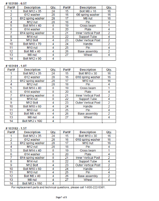

Points to take away from document 2:
Sections to include in the following pages:
Overall design of crane components
• Outlining the overall design of the crane components
• Details drawings of each component
Construction of crane using the kit of parts
• Exploded view (use for reference to where each part from the kit fits)
• Fitness for purpose of each part
• Assembly
• Maintenance
• Safety
Finance and costs of each kit
• breakdown of the cost of each kit
• contract cost for 100 cranes
• Commercial costs for primarily government bodies (opportunity)
• Licensing kits to third parties (opportunity)
The purpose for the following two documents are to be used by the materials specialist and the stress analyst as a template in order to complete section "Section 3 - Construction of crane using the kit of parts":
Document 1


Points to take away from document 1:
- use a manual type format
- include diagrams with warnings to the user for general issues with putting together the crane, safety... and can use different colours (i.e red) to put emphasis on the importance of the text.
- Logo
- Assembly instructions
- Operating instructions
- Loading capacity
- Any extra tools required for assembly
Document 2


Points to take away from document 2:
- Provide a table with a list of components and refer the location of each part of the crane by using a labelled exploded view diagram
- Notes on crane maintenance
- Notes on operation
- Personal safety notes and workspace safety
- Warning labels
Friday, 9 April 2010
LIST
The following course of action will take place in order to finish work on the crane:
Design (Mark)
1. Need an exploded view of the design to see where each of the separate parts fit into the final assembly
2. Need to check/change some of the dimensions – e.g. boom to fit the UB 178x102x19 standard sizes and check the sizes of some of the struts for the legs to make sure there is enough clearance for overlapping parts
3. Check and select most appropriate design ideas from the posted list “changes to design” and apply to cad design
4. Find standard bolt and nut dimensions as some thread dimensions are not long enough to fit the nut, (consider extra space for a spring washer - to relieve friction, prevent loosening or distribute pressure) – (Jason & Jarrett provide assistance)
5. Post up the pages of the initial design sketches leading to the final crane design
6. Begin working on individual report section
Materials and analysis (Jason & Jarrett)- needs to be done BY MONDAY!!
1. Calculate the remaining stress values on the legs
2. Select a suitable aluminium alloy for the legs and calculate the mass- pass onto Abdi
3. For the selected structural steel grade S355 for the boom- find costs to assist Abdi
4. Calculate stress' on bolts/pins
5. Begin working on individual report section
Costs (Abdi)
Costs for aluminium alloys and steel
Bolts...
Changes to design
Certain design features which need to be brought to the attention of the group, as could potentially reduce stresses on certain structures, increase stability or for safety. The following cases for consideration will be brought up in the next meeting:
The following alteration must be made:

Obtained from BS5950-12000part1
Nut and Bolt

Leg design

Hole design -choice

Matts

The following alteration must be made:

Obtained from BS5950-12000part1
Nut and Bolt

Leg design

Hole design -choice

Matts

Recently discovered issues with the IPE160 beam and alternative solutions
For the given types of load exerted on the standard IPE160 beam the deflection, BMmax and SFmax were obtained to indicate worst case conditions that the given material (steel grade) would need to withstand:

The next stage was to calculate the maxBM and maxSF for the given structural steel. If these values are found to be higher than the calculated maxBM and maxSF under load then the beam will not fail. The following formulas were used:
M = Z *("fy") where Z = I/y (for the moment)
Where “fy” = steel grade
V= "dw"*"tw"*("fy"/(3)^(1/2)) (for the shear force)
Formulas and following information courtesy of:
The Corus interactive “blue book” to BS 5950-1
BS 4: part1:1993
BS 5950-12000 part 1
Elements of Strength of Materials, International Student Edition, by S Timoshenko
To calculate the maxBM:
M = Z ("fy")
Note:
Z = I/y and y= D/2
“fy”= common steel grade S250= 250 N/mm^2
( i.e for the given 5mm thickness the required design strength is 250N/mm^2)

I=8.34E-06 m^4 or 8.34E+06 mm^4
D/2 =160mm/2= 80mm
Therefore Z =I/y = (8.34E+06 mm^4/80mm)
Z =104250mm^3
M=Z* “fy”
M=104250mm^3 * 250 N/mm^2
M=26.06E+06 Nmm
M=26.06 kNm
In order to obtain the maxBM a factor of safety rm=1.05 and rf=1.1 provided in the Corus interactive “blue book” to BS 5950-1 need to be included:
Md =M/rm*rf
Md =26.06/1.05*1.1
Md =22.5 kNm
This is the maxBM that this steel grade could withstand.
For max shear force that the beam would need to withstand:
V ="dw"*"tw"*("fy"/(3)^(1/2))
V= 5* 145.2*(250/(3)^(1/2))
V=104789N or 104.789kN
However another factor mentioned in the Corus interactive ” blue book” is to have a safety capacity related to Buckling (some tables are given ):

Therefore a major issue with this beam is the maxBM allowable due to consideration of safety factors and buckling.
Further research also found IPE160 to be a castellated beam type which further impacts on strength but also increases the general cost of the material.
To obtain a more suitable beam a different standard will be used and a steel grade S355:
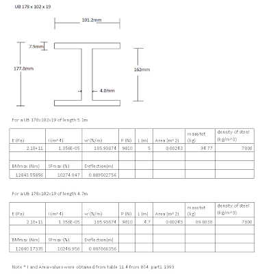
The next stage was to calculate the maxBM and maxSF for the given structural steel. If these values are found to be higher than the calculated maxBM and maxSF under load then the beam will not fail.
I=1.356E-05 m^4 or 1.356E+07 mm^4
D/2 =177.8mm/2= 88.9mm
Therefore Z =I/y = (1.356E+07 mm^4/88.9mm)
Z=152530.9336mm^3
M=Z* “fy”
M=152530.9336mm^3 * 355 N/mm^2
M=54.148E+06 Nmm
M=54.148 kNm
In order to obtain the maxBM a factor of safety rm=1.05 and rf=1.1 provided in the “blue book” to BS 5950-1 need to be included:
Md =M/rm*rf
Md =54.148/1.05*1.1
Md =46.881 kNm
This is the maxBM that this steel grade could withstand.
For max shear force that the beam would need to withstand:
V ="dw"*"tw"*("fy"/(3)^(1/2))
V= 4.8* 146.8*(355/(3)^(1/2))
V=144422.553N or 144.423kN
However another factor mentioned in the Corus interactive "blue book” is to have a safety capacity related to Buckling (the following value is from table “4.1.3. bending. Advance UKB. Moment capacity and buckling resistance moment for Advance 355”):
Md =17kNm

This beam clearly passes the basic required criteria and so long as these loading conditions are maintained it should not fail for the duration of the service for the disaster relief (if a 4.7m beam were to be used the buckling resistance moment would be higher than 17kNm).
The following are the lists of tables used from the BS standards :


The next stage was to calculate the maxBM and maxSF for the given structural steel. If these values are found to be higher than the calculated maxBM and maxSF under load then the beam will not fail. The following formulas were used:
M = Z *("fy") where Z = I/y (for the moment)
Where “fy” = steel grade
V= "dw"*"tw"*("fy"/(3)^(1/2)) (for the shear force)
Formulas and following information courtesy of:
The Corus interactive “blue book” to BS 5950-1
BS 4: part1:1993
BS 5950-12000 part 1
Elements of Strength of Materials, International Student Edition, by S Timoshenko
To calculate the maxBM:
M = Z ("fy")
Note:
Z = I/y and y= D/2
“fy”= common steel grade S250= 250 N/mm^2
( i.e for the given 5mm thickness the required design strength is 250N/mm^2)

I=8.34E-06 m^4 or 8.34E+06 mm^4
D/2 =160mm/2= 80mm
Therefore Z =I/y = (8.34E+06 mm^4/80mm)
Z =104250mm^3
M=Z* “fy”
M=104250mm^3 * 250 N/mm^2
M=26.06E+06 Nmm
M=26.06 kNm
In order to obtain the maxBM a factor of safety rm=1.05 and rf=1.1 provided in the Corus interactive “blue book” to BS 5950-1 need to be included:
Md =M/rm*rf
Md =26.06/1.05*1.1
Md =22.5 kNm
This is the maxBM that this steel grade could withstand.
For max shear force that the beam would need to withstand:
V ="dw"*"tw"*("fy"/(3)^(1/2))
V= 5* 145.2*(250/(3)^(1/2))
V=104789N or 104.789kN
However another factor mentioned in the Corus interactive ” blue book” is to have a safety capacity related to Buckling (some tables are given ):
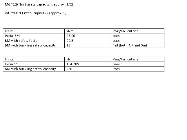
Therefore a major issue with this beam is the maxBM allowable due to consideration of safety factors and buckling.
Further research also found IPE160 to be a castellated beam type which further impacts on strength but also increases the general cost of the material.
To obtain a more suitable beam a different standard will be used and a steel grade S355:

The next stage was to calculate the maxBM and maxSF for the given structural steel. If these values are found to be higher than the calculated maxBM and maxSF under load then the beam will not fail.
I=1.356E-05 m^4 or 1.356E+07 mm^4
D/2 =177.8mm/2= 88.9mm
Therefore Z =I/y = (1.356E+07 mm^4/88.9mm)
Z=152530.9336mm^3
M=Z* “fy”
M=152530.9336mm^3 * 355 N/mm^2
M=54.148E+06 Nmm
M=54.148 kNm
In order to obtain the maxBM a factor of safety rm=1.05 and rf=1.1 provided in the “blue book” to BS 5950-1 need to be included:
Md =M/rm*rf
Md =54.148/1.05*1.1
Md =46.881 kNm
This is the maxBM that this steel grade could withstand.
For max shear force that the beam would need to withstand:
V ="dw"*"tw"*("fy"/(3)^(1/2))
V= 4.8* 146.8*(355/(3)^(1/2))
V=144422.553N or 144.423kN
However another factor mentioned in the Corus interactive "blue book” is to have a safety capacity related to Buckling (the following value is from table “4.1.3. bending. Advance UKB. Moment capacity and buckling resistance moment for Advance 355”):
Md =17kNm

This beam clearly passes the basic required criteria and so long as these loading conditions are maintained it should not fail for the duration of the service for the disaster relief (if a 4.7m beam were to be used the buckling resistance moment would be higher than 17kNm).
The following are the lists of tables used from the BS standards :


Saturday, 3 April 2010
references for calculations
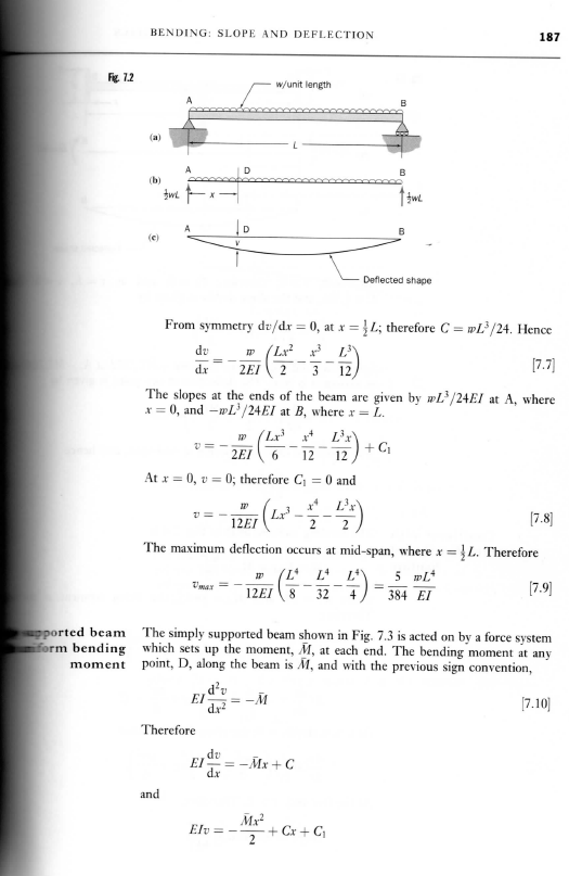
The following scanned images are from 2 selected books which have been used to obtain the equations used to calculate the stresses and deflections for the boom.
Courtesy of:
Mechanics of engineering materials, second edition, by PP Benham, RJ Crawford & CG Armstrong;
Elements of Strength of Materials, International Student Edition, by S Timoshenko;
In order to obtain the following equations in the calculations:

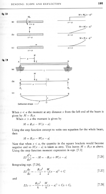
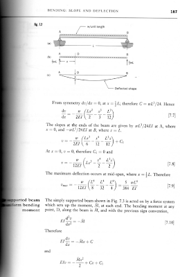
A formula sheet from "Elements of Strength of Materials, International Student Edition, by S Timoshenko" where by the principle of superposition two factors (deflection due to a uniformly distributed load and deflection due to a point load) were combined providing the final deflection value.

The theory of superposition is explained in the following paragraphs along with the diagrams provide a visual image of how the beam will behave when subjected to varying loads (this is an important situation as it's behaviours in the following example are very similar to the behaviours we could expect our crane to experience):


The following scans are proofs of the formula obtained for the varying deflection loads and can be used as a template for our mathematical equations (for double checking values or if an error was made in the final value where could it have occurred by following the template).
For a point load our calculations would need to follow the following format:

For a uniformly distributed load the calculations would need to follow the following format:

For the particular type of I beam our crane will be using, due to the shape we have selected, it was required to use the following formula for is second moment of area.

However in order to find the maximum bending moment and the maximum shear force the following diagrams were used along with the knowledge that maximum bending moment will occur when the 1000kg load is placed in the middle of the beam and that the max shear force when the load is placed at its ends:


the diagrams and calculations allowed through the theory of superposition to combine:
for max shear:
Pa/l (for point load where a=l)+ wl/2 (uniform load)
therefore obtaining the equation: wl/2 + P
for max BM:
(Pab)/l (for point load where a=l/2 and b=l/2) + (wl^2)/8
Therefore obtaining the equation: (wl^2)/8 +Pl/4
The final thing which would need to be calculated is the max BM and SF that the particular beam we have selected can handle due to its dimensions and type of structural steel component. ( if these values are higher than the ones obtained for the calculations that our beam will create with its load, it will mean the beam is safe to use under these conditions as it will not fail under them):


the following equations will be used:
M = Z ("fy") where Z = I/y (for the moment)
V= "dw""tw"("fy"/(3)^(1/2))
"fy"= specific design strength of the steel selected from a list of steel grades (e.g. are given on previous blogs)
Another factor that could be calculated in its stead includes the working stress at a distance point y. It would need to be found using the yield point or ultimate tensile stress for that particular grade of steel and divide it by a safety factor e.g. 2 (as given in the example). This will ensure that the steel will remain in the safe elastic region and avoid becoming permanently deformed.
Courtesy of:
Mechanics of engineering materials, second edition, by PP Benham, RJ Crawford & CG Armstrong;
Elements of Strength of Materials, International Student Edition, by S Timoshenko;
In order to obtain the following equations in the calculations:

A formula sheet from "Elements of Strength of Materials, International Student Edition, by S Timoshenko" where by the principle of superposition two factors (deflection due to a uniformly distributed load and deflection due to a point load) were combined providing the final deflection value.

The theory of superposition is explained in the following paragraphs along with the diagrams provide a visual image of how the beam will behave when subjected to varying loads (this is an important situation as it's behaviours in the following example are very similar to the behaviours we could expect our crane to experience):


The following scans are proofs of the formula obtained for the varying deflection loads and can be used as a template for our mathematical equations (for double checking values or if an error was made in the final value where could it have occurred by following the template).
For a point load our calculations would need to follow the following format:


For a uniformly distributed load the calculations would need to follow the following format:

For the particular type of I beam our crane will be using, due to the shape we have selected, it was required to use the following formula for is second moment of area.

However in order to find the maximum bending moment and the maximum shear force the following diagrams were used along with the knowledge that maximum bending moment will occur when the 1000kg load is placed in the middle of the beam and that the max shear force when the load is placed at its ends:


the diagrams and calculations allowed through the theory of superposition to combine:
for max shear:
Pa/l (for point load where a=l)+ wl/2 (uniform load)
therefore obtaining the equation: wl/2 + P
for max BM:
(Pab)/l (for point load where a=l/2 and b=l/2) + (wl^2)/8
Therefore obtaining the equation: (wl^2)/8 +Pl/4
The final thing which would need to be calculated is the max BM and SF that the particular beam we have selected can handle due to its dimensions and type of structural steel component. ( if these values are higher than the ones obtained for the calculations that our beam will create with its load, it will mean the beam is safe to use under these conditions as it will not fail under them):


the following equations will be used:
M = Z ("fy") where Z = I/y (for the moment)
V= "dw""tw"("fy"/(3)^(1/2))
"fy"= specific design strength of the steel selected from a list of steel grades (e.g. are given on previous blogs)
Another factor that could be calculated in its stead includes the working stress at a distance point y. It would need to be found using the yield point or ultimate tensile stress for that particular grade of steel and divide it by a safety factor e.g. 2 (as given in the example). This will ensure that the steel will remain in the safe elastic region and avoid becoming permanently deformed.
Subscribe to:
Posts (Atom)