I believe this project went well and that we worked well as a team. We remained on schedule for the first stage and , due to continuous work from the group over the Easter holidays, were able to complete the project on time despite some set backs.
The greatest problem we faced was that two of our group members were missing for approximately three weeks each at different stages of the project. Our materials specialist was absent due to illness at the start of the project, and our stress analyst was not contactable over the Easter holidays due to a breakdown in communication. The remaining group members however worked well around these losses and those who did miss part of the project worked hard upon their return to make up for their loss, in order to produce the final crane to a high standard.
The second set back occurred towards the start of the Easter break when it was realised that the main beam needed redesigning. This set us back about a week, though did give us the opportunity to redesign the beam to British standard dimensions.
The greatest flaw in the design that was picked up in the Q&A section of the presentation was that the beam, at 5.5 metres in length, was on the border of being impractically large. This was a problem that we had considered, though splitting the beam would have weakened it significantly. If I had more time for this project , I would spend much of it considering possible solutions to splitting the beam. In addition, the design of the head piece of the shoulder component would be difficult to manufacture for a reasonable cost.
In conclusion, though we had a few issues, I believe this project was a success, and that we completed it to a high standard as well as to specification.
Friday, 30 April 2010

Thursday, 29 April 2010
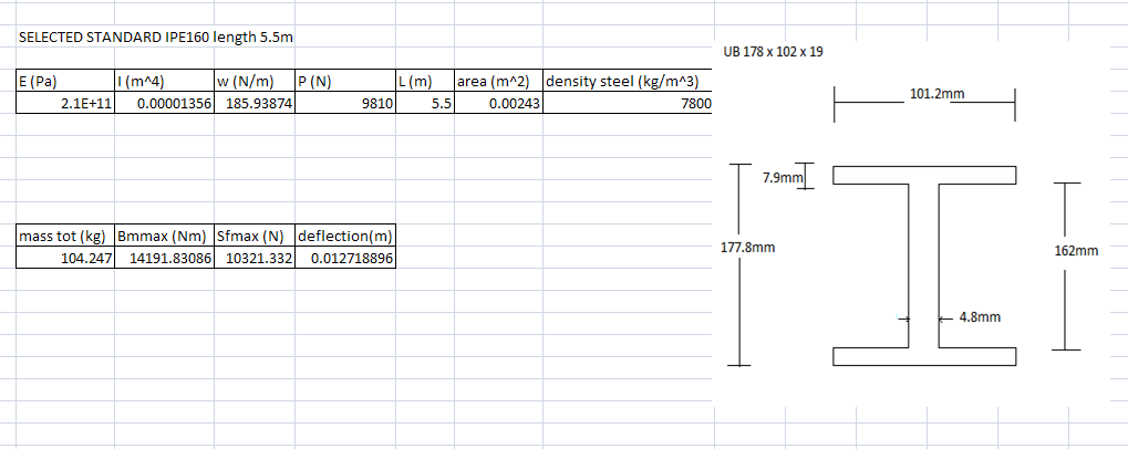
Final dimension sizes for I beam

Exploded crane animation
This is the animation describing the assembly of the crane.
The colour scheme is arbitrary in this video, designed to allow the viewer to differentiate easily between components.
Safety - Tools
It is highly advisable to tighten the U-bolts by hand with a spanner rather than with a torsion torsion wench. It is also advisable to use a spirit level to ensure that the beam is horizontal before loading the crane to minimise the chances of the hoist slipping along the beam.
Tuesday, 27 April 2010
Revised Calculations
From the analysis done to work out how much length was needed for an object to move 4m maximum from one point to another it was calculated that the beam would have to be a minimum standard length of 5.5m
Revising the calculations done at an earlier date a delfection of 12.29mm was established with the same CSA.
Revising the calculations done at an earlier date a delfection of 12.29mm was established with the same CSA.
Sunday, 25 April 2010
Company Name and Logo
The company name chosen was Dynamic Engineering Solutions (DES). This name is both memorable and slightly amusing, though the comical effect wears off the more one hears it thus allowing are clients to take our company seriously once the initial attention catching humour wears off. The logo chosen utilises primary colours in order to grab attention in an aesthetically pleasing manor. The image below shows the logo for official correspondence.

 The final orientation of the company logo is the squared off version design to be placed on CAD drawings and on our products. This logo, depicted below, is both bold and instantly recognisable. It is designed so that perspective clients will be attracted to our company when they see it in the field.
The company motto will be added to this design for our advertising. The motto required a short, memorable, and to-the-point sentence to sum up our companies values, and inspire the trust of our perspective clients.
The motto chosen was "just ask DES", which was designed to imply that we shall go above and beyond to satisfy our clients needs whatever they may be. The image below depicts the company logo with the motto attached.
The final orientation of the company logo is the squared off version design to be placed on CAD drawings and on our products. This logo, depicted below, is both bold and instantly recognisable. It is designed so that perspective clients will be attracted to our company when they see it in the field.
Saturday, 24 April 2010
Formal Engineering Drawings Templates
The follow image is the engineering drawing template for the crane components. The company logo is yet to be inserted, but all other elements are as they will be in the formal proposal.
 The next image is of the engineering drawing template for the crane assemblies, one will be standard and the other one will be exploded.
 This drawing template also requires the company logo, though is also otherwise as the final assembly drawings will be presented.
The blue text represents links to the part designs, which will be automatically replaced with the appropriate information.
The next image is of the engineering drawing template for the crane assemblies, one will be standard and the other one will be exploded.This drawing template also requires the company logo, though is also otherwise as the final assembly drawings will be presented.The blue text represents links to the part designs, which will be automatically replaced with the appropriate information.
Subscribe to:
Posts (Atom)